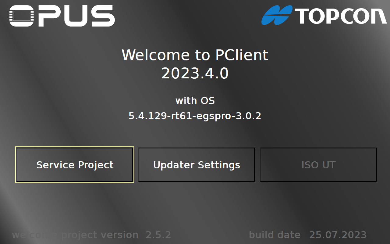
When you install a PClient on a device, you will see the following welcome project (the versions shown on the display may differ).
Please note that the welcome project is also available as a sample project.
No Touch Mode
If your device has no input method, i.e. no keys and no touch, the welcome project will start in a no touch mode.
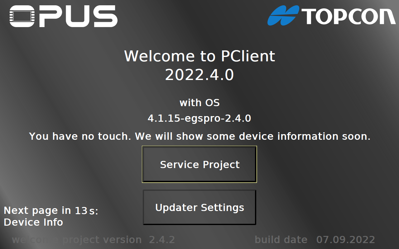
In this mode, the project will show different screens to show some information about the device. The pages are
Home page -> Device Info -> Sensors -> Power Modes -> Power Mode Time Settings -> Power Modes Configuration -> Info to USB
There will be a counter in the lower left, showing when the next page will be shown. The next page will be written there, as well.
On the Info to USB page it is possible to copy the information files to the USB stick by disconnecting the ignition for a short time (just a couple of seconds, make sure you reconnect before the low-power time out time).
Updater Settings
By pressing the Updater Settings button you can navigate to the Updater Settings page.
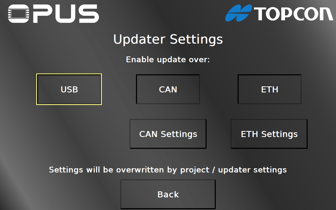
On this page you can enable / disable the project download over USB, CAN and ETH (Ethernet) by pressing the according buttons. Pressing them again will inverse the current setting. By pressing the CAN Settings button you can navigate to the CAN Settings page. By pressing the ETH Settings button you can navigate to the Ethernet Settings page. Both settings buttons will only be visible when the according transfer medium is enabled.
Back returns to the main welcome page.
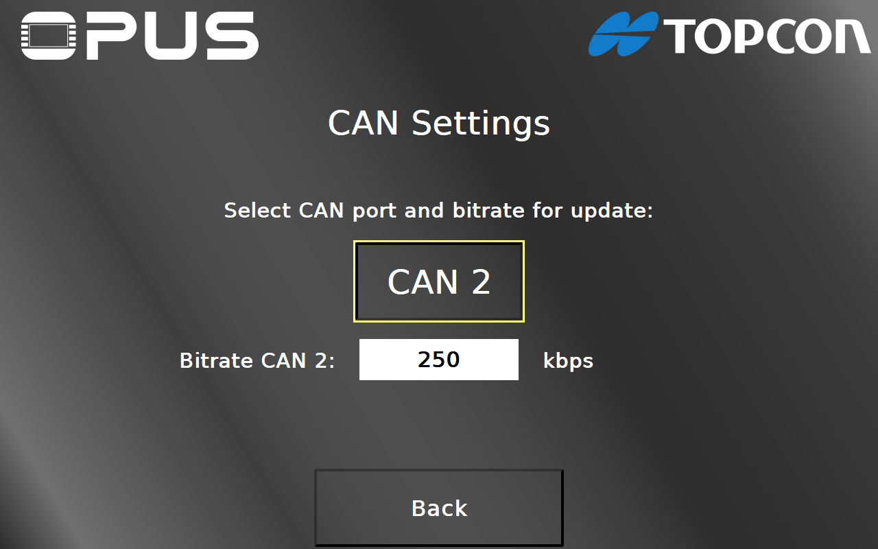
On the CAN Settings page you can set the CAN port that should be used for the project download and the Bitrate for the project download for that port.
Back returns to the Updater Settings page.
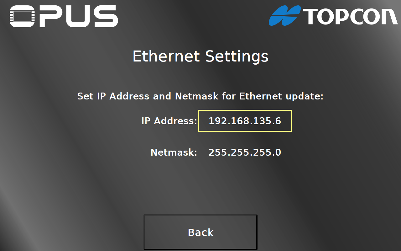
On the Ethernet Settings page you can set the IP Address (10) and Netmask (11) that the device should have in the network. With the Back button (12) you can go back to the Updater Settings page.
Please note: All settings made in this project are temporary and only valid for the first project transfer. All settings will be overwritten by settings in the transferred project.
You should make the according settings in the project you want to transfer to the device:
- The variable @EnableUpdater variable controls which update is allowed
- The CAN bus bitrate will be taken from the bitrate set in the transferred project
- The CAN port used for the transfer can be set with the variable @CANx_Bitrate
- The IP address can be set with the variable @Ethernet0_IPAddress
- The Netmask can be set with the variable @Ethernet0_Netmask
Back returns to the Updater Settings page.
Service Project
By pressing the Service Project button you can navigate to the Service Project main page.
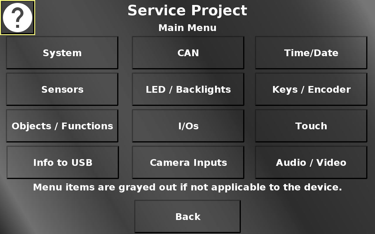
In this screen the different main menu items can be chosen. Back returns to the main screen.
You can press the main menu buttons in this image to jump to the according part of the topic.
On every page, a help button is available, which gives a short explanation what can be done on the page.
Menu items, behind which there are only features that are not available for the current device will be grayed out. It is still possible to go into the according pages or use the according buttons, but nothing will happen or work.
On most pages in the Service Project an "Eject USB" button will be displayed next to the help button if a USB stick is connected to the device. If you want to unplug the USB stick, press this button first to unmount it properly from the device.
Service Project -> System
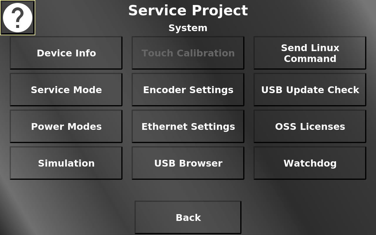
In this screen different system information and system settings can be chosen.
You can press the main menu buttons in this image to jump to the according part of the topic.
Back returns to the main menu.
Service Project -> System -> Device Info
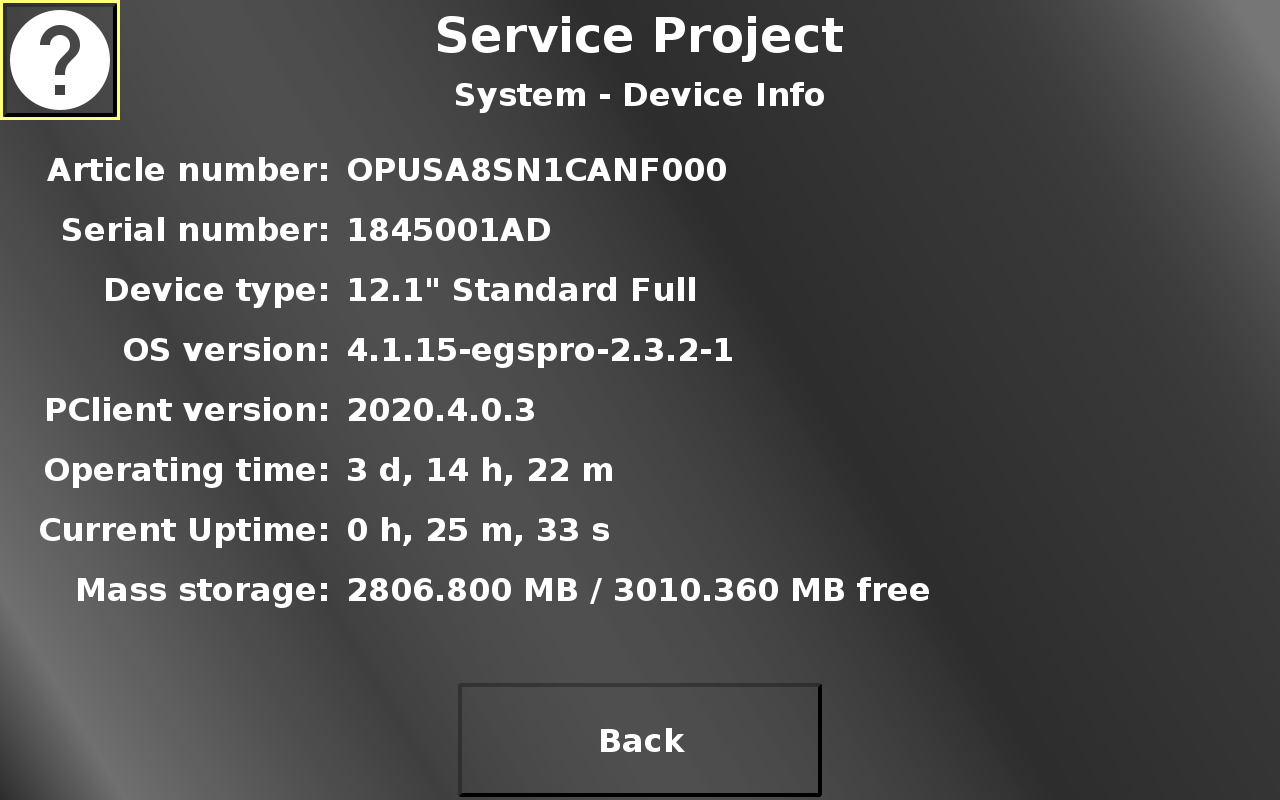
In this screen different device data is displayed. Back returns to the system menu.
Service Project -> System -> Service Mode
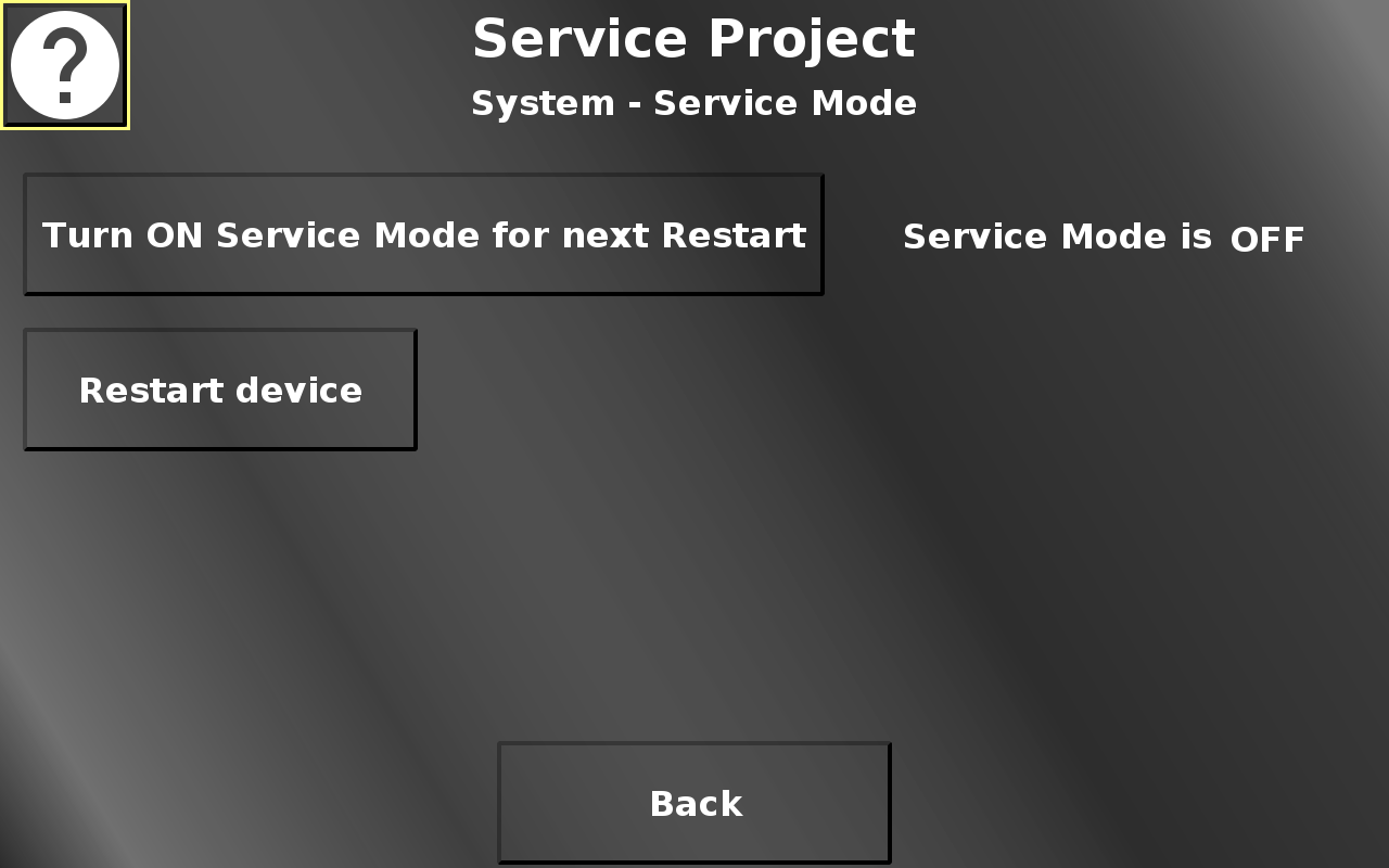
In this screen the service mode can be activated for the next reboot to update OS / PClient.
Pressing the restart button opens a confirmation dialog.
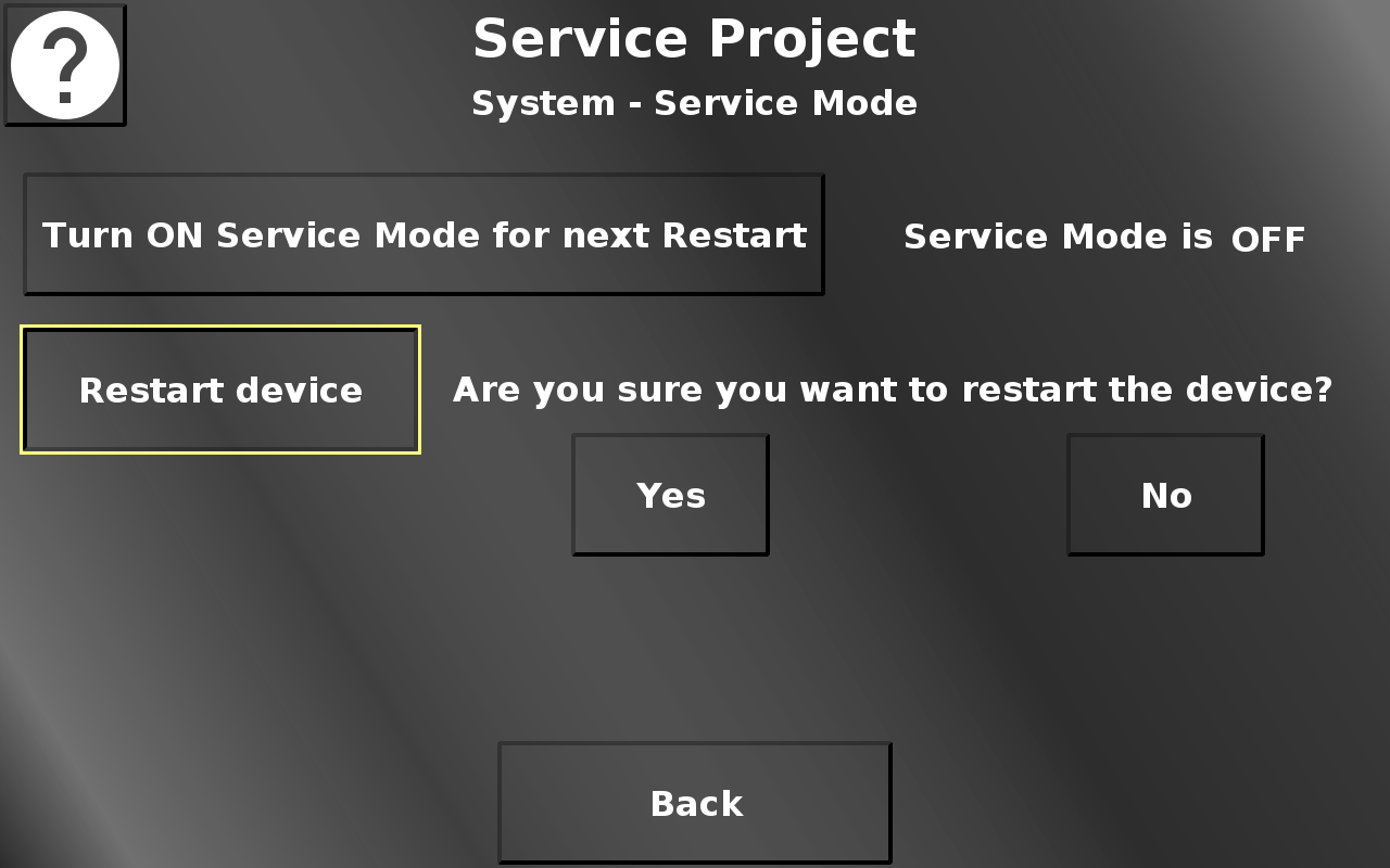
By pressing Yes the device will reboot. By pressing No the dialog will be closed again. The service mode setting will be kept. Back returns to the system menu.
Service Project -> System -> Power Modes
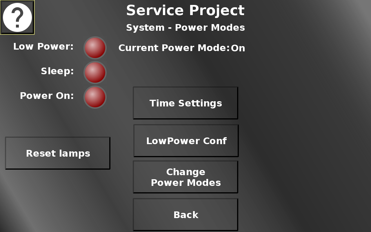
In this screen the different power events can be tested. The current power mode is shown in the top. The lamps will light up when the according power event is used. Disconnect clamp 15 /ignition pin to enter low-power mode, and then sleep mode, after which the device will turn off. Reset lamps turns all lamps off.
Additionally, three configuration screens can be entered. Time settings allows setting the times for the different power modes. LowPower Conf leads to a page where hardware elements can be configured for the low-power mode. On Change Power Modes some power modes can be entered.
Back returns to the system menu.
Service Project -> System -> Power Mode Time Settings
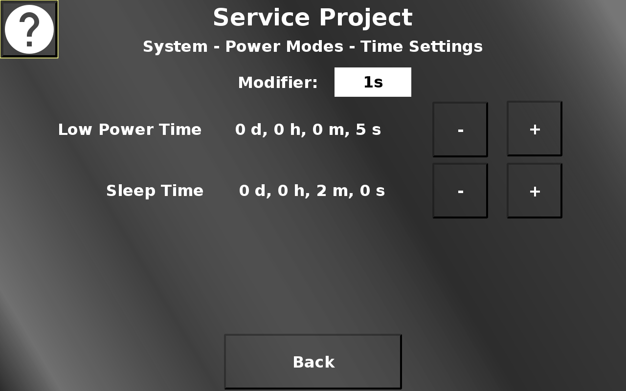
In this screen the times for the low-power mode and the sleep mode can be set. - (minus) decreases the time, + (plus) increases the time. For some devices, the silent on to low power time can be set, as well. The amount that the current value is modified by, can be chosen with the modifier drop down. Back returns to the Power Modes screen.
Service Project -> System -> Low Power Configuration
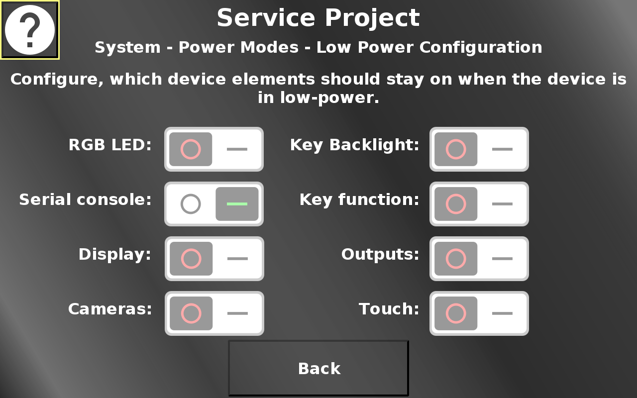
In this screen, hardware elements can be configured to stay on or turn off when low power mode is entered. If the switch is in the OFF position, the element will turn off when low-power mode is entered. If the switch is in the ON position, the element will stay on in low-power mode.
Back returns to the power mode screen.
Service Project -> System -> Change Power Modes
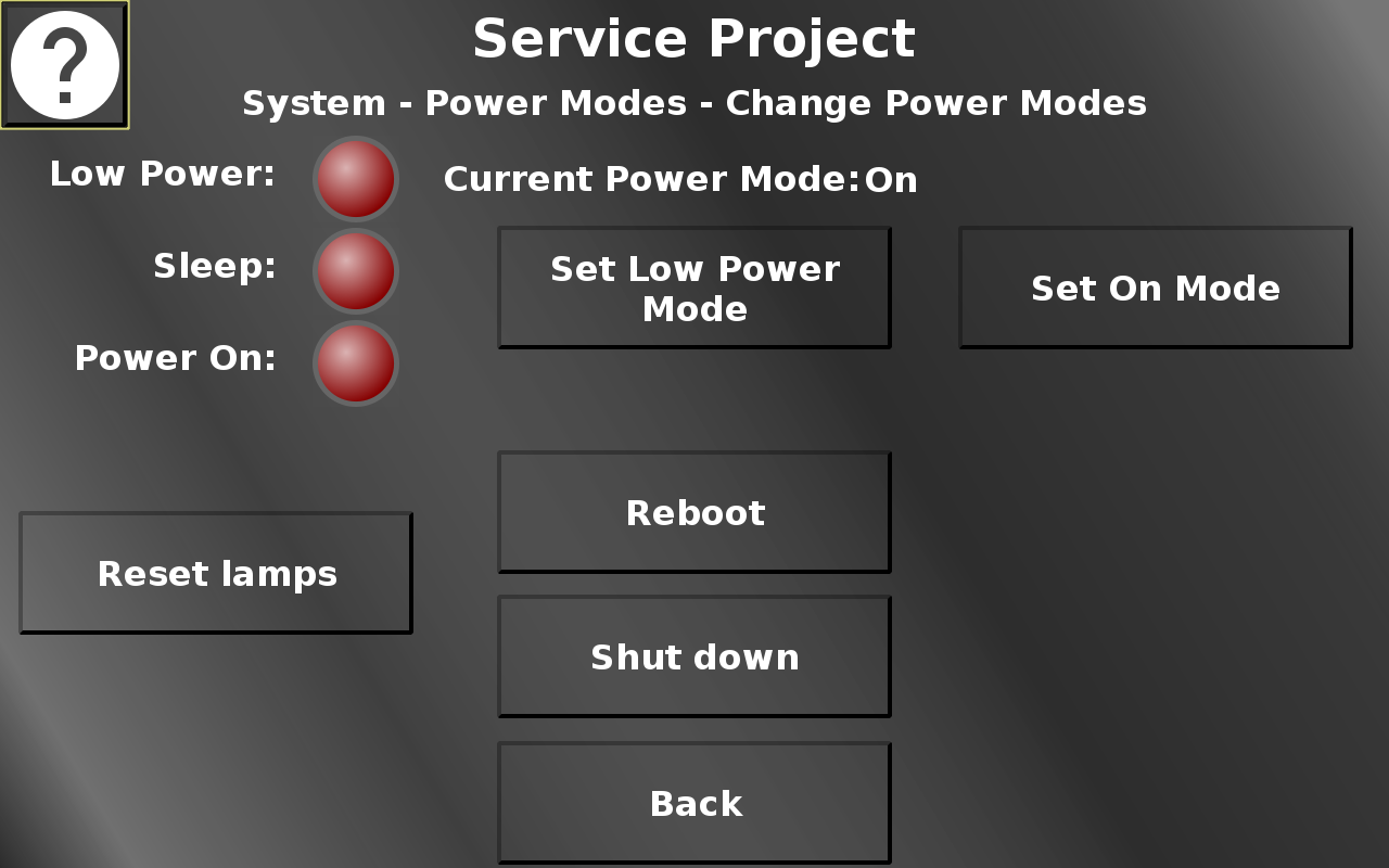
In this screen different power modes can be activated. Low power and on mode can be set here. For some devices, a timed low power mode can be set, as well. For both low power modes a pop up will be shown, warning that a way back to on mode should be considered, either by disconnecting and re-connecting ignition, or by setting display, touch and or keys to still work in low power mode. Additionally, the device can be rebooted and shut down. The lamps and the current mode are identical to the power mode screen.
Back returns to the power mode screen.
Service Project -> System -> Simulation
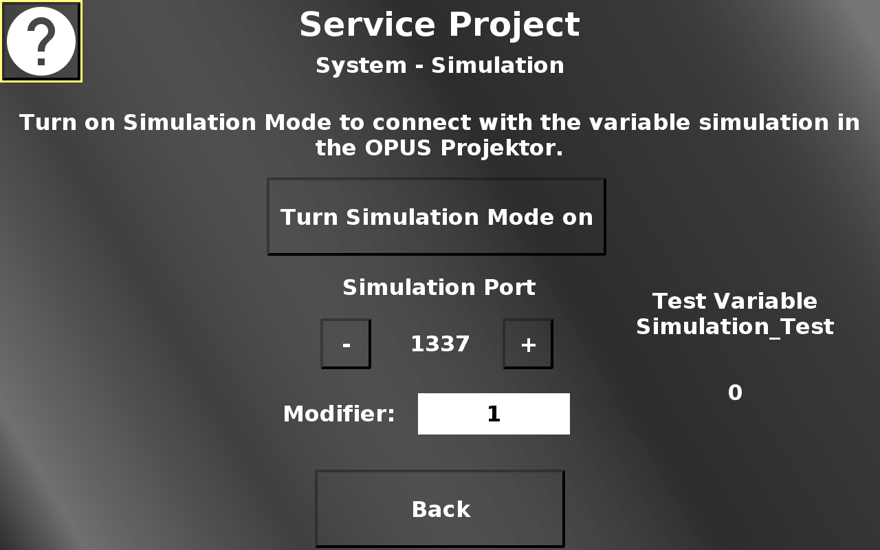
In this screen the simulation mode can be enabled to be able to use the variable simulation in the OPUS Projektor for the device.
Additionally, the port for the simulation can be set by pressing the - (minus) and + (plus) buttons.
The modifier drop down chooses the value by which the - and + buttons change the port value.
Back returns to the system menu.
Service Project -> System -> Touch Calibration
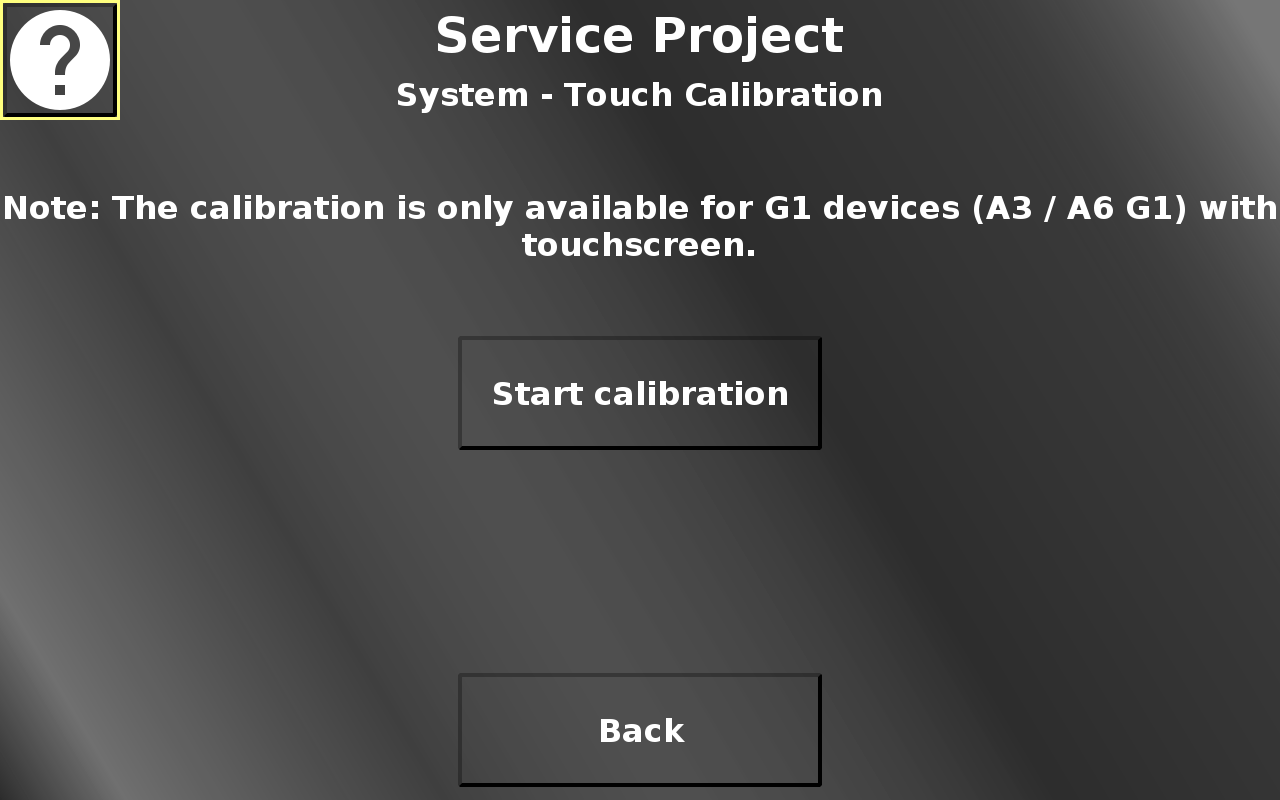
In this screen the touch screen calibration can be started. 5 cross hairs will appear one after another (top left, top right, bottom right, bottom left, center). Press the cross hairs to calibrate the screen.
Please note that the PClient stays on during this operation, so the cross hairs will be painted over this screen.
Please note that the calibration is only available for A3/A6 G1 touch screens. Devices with capacitive touch screens do not neet this calibration.
Back returns to the system menu.
Service Project -> System -> Encoder Settings
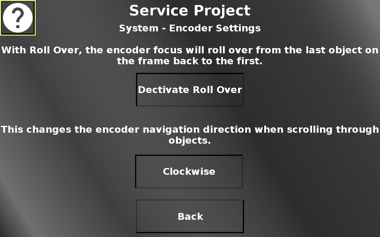
In this screen two encoder settings can be made.
Roll over means that the yellow selection rectangle will not stop at the last object, but it will roll over to the first object again.
Additionally, the navigation direction for the encoder can be switched between clockwise and anti-clockwise.
Back returns to the system menu.
Service Project -> System -> Ethernet Settings
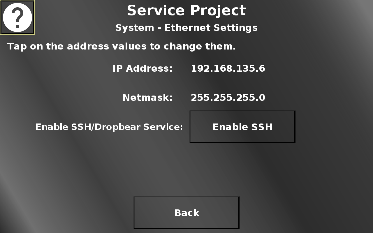
In this screen, the IP address and Netmask can be set, similarly to the updater screen described above.
Additionally, SSH can be enabled here. On devices with Automotive Ethernet, the mode can be switched between master and slave here, as well.
Back returns to the system menu.
Service Project -> System -> USB Browser
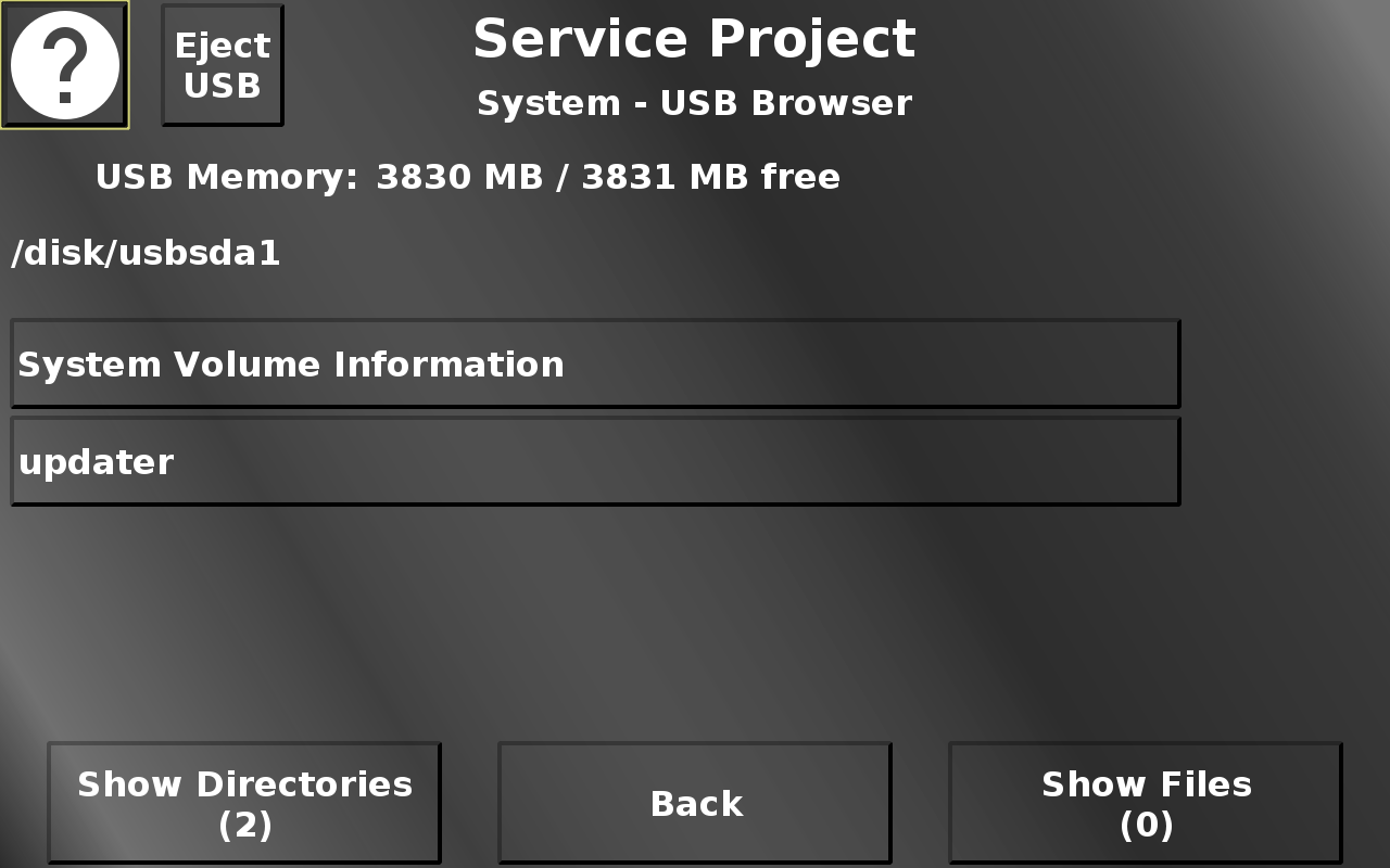
In this screen a rudimentary USB file browser is implemented. If a USB stick with a valid file system is plugged in, the content will be shown. Next to the help button, an eject/unmount button will be shown to unmount the USB stick before unplugging it. The view in the browser can be switched between directories and files.
For directories, a press of the according button will show the content of this directory. The current path is shown in the top of the screen. When directories are enterered, a "back" button will be displayed to go back up to the root of the USB stick. Both for files and directories, "up" and "down" buttons will be shown if more than 4 directories / files are present in the current directory.
For files, a button press will open an alarm with a preview of the file. For image files the image will be shown. Note that the aspect ratio will not be correct. For compatible audio and video files an alarm with a multimedia player will be shown to play the file. Note that the aspect ratio of the video will not be correct. For pdf files the pdf reader will be opened. For all other file types the beginning of the file (up to 2MB) will be shown as text. The text can be scrolled to see more content. Back returns to the system menu.
Service Project -> System -> Send Linux Command
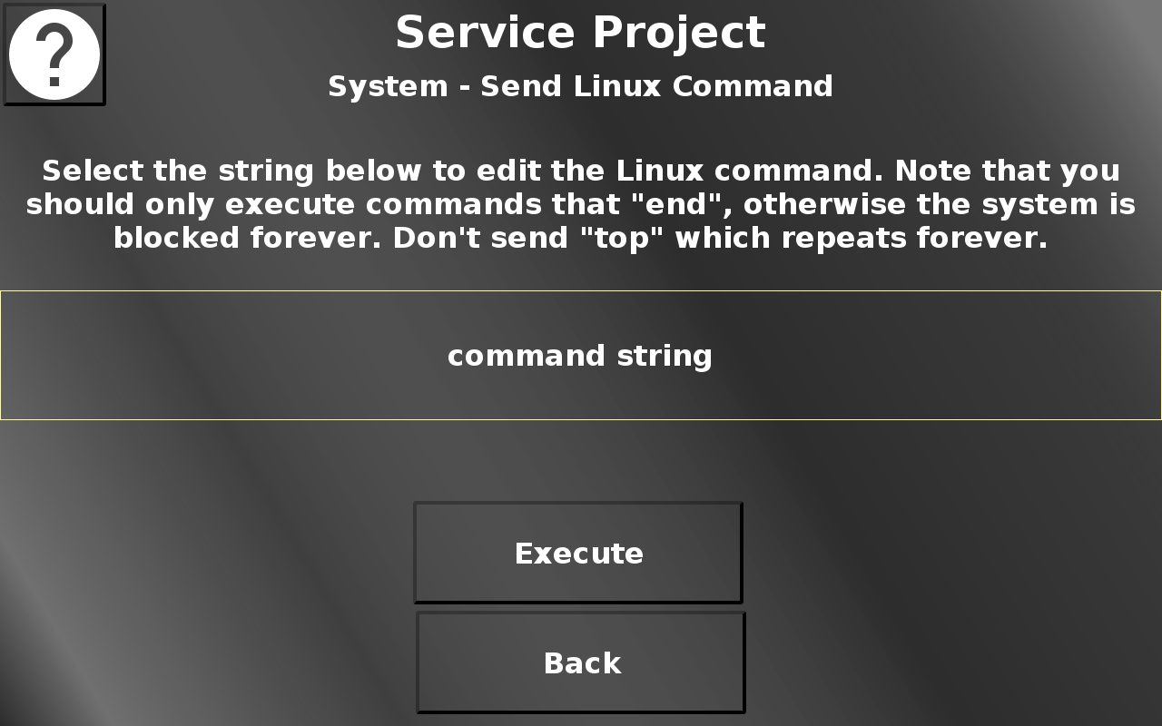
In this screen a Linux command can be executed. Select the field that says "command string" and a virtual keyboard will open. Enter a command of your choice. With the Execute button the command will be executed in the Linux system. If the command is faulty, it will be displayed that there was an error executing this command.
Please note that only valid commands should be entered, and only commands that will finish in a finite time. Since the execution of the command is done in JavaScript, the PClient will wait until the Linux command has finished before continuing. So a simple command like "top" will lead to a non-reactive device, because top will show the CPU usage of the processes and refresh that forever. In such a case the device has to be rebooted.
Back returns to the system menu.
Service Project -> System -> USB Update Check
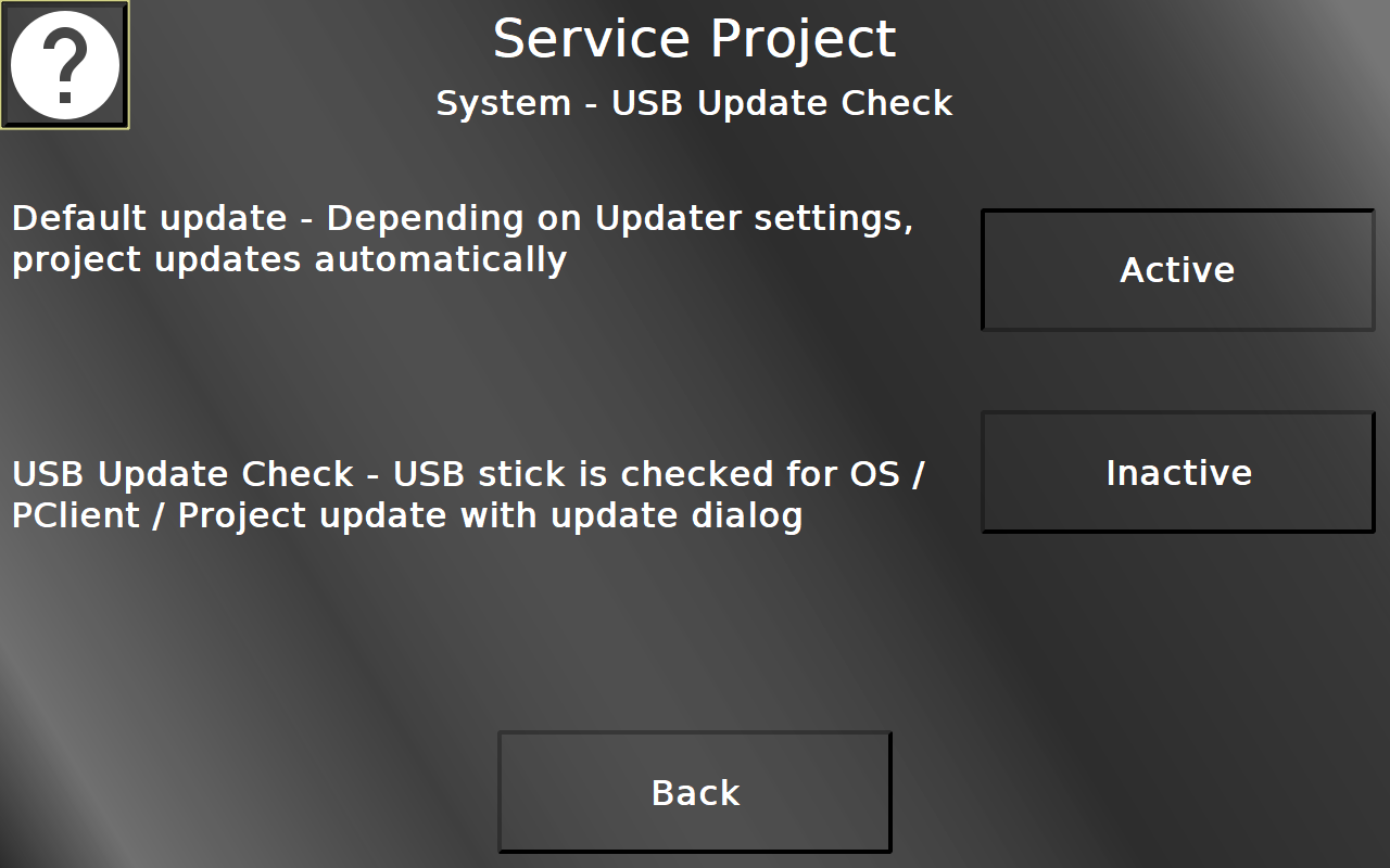
In this screen the update behavior when inserting a USB stick can be selected. The default update option (active by default) is the behavior as you know it - when a USB stick with a project is inserted and USB update is enabled in the Updater section, the project will be loaded.
With the USB Update Check the behavior will be different. If a USB stick is inserted, it is checked whether the USB stick contains a project and/or OS/PClient files. If it contains either of those, a pop up alarm will be displayed, giving the options to load the project or to reboot in service mode to install the OS / PClient files.
Back returns to the system menu.
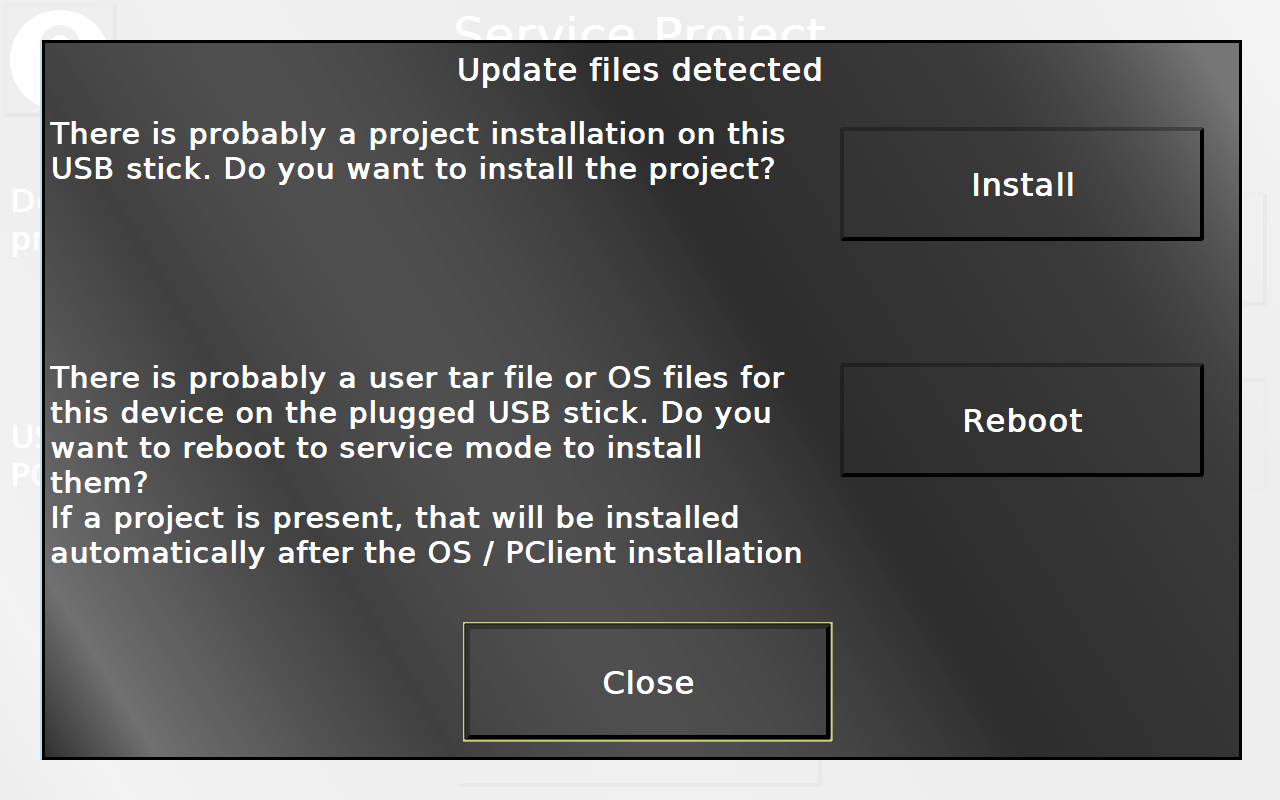
By pressing Install, the project on the USB stick will be installed.
By pressing Reboot, after a confirmation the device will be rebooted in service mode in which the OS / PClient files will be installed. Note that afterwards the device reboots again, starts in service mode, and if a PClient is installed and a valid project is on the USB stick, that project will be installed automatically, since the USB Update Check settings are volatile.
Close will return to the page that was shown before.
Service Project -> System -> Open Source Software Licenses
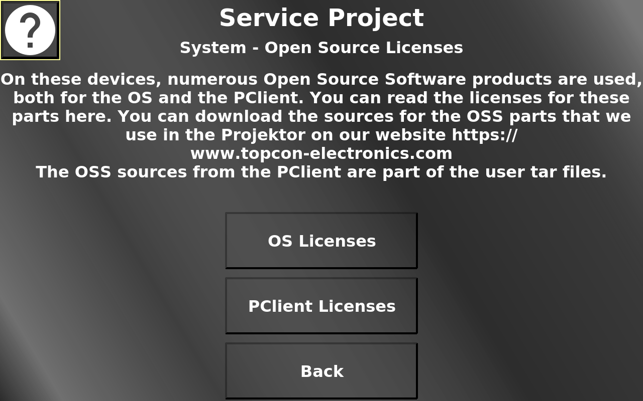
In this screen the open source licenses from the OS and the PClient can be viewed. Pressing the OS Licenses button shows the OS Licenses, pressing the PClient Licenses button shows the PClient licenses.
Back returns to the system menu.
Service Project -> System -> Open Source Software Licenses -> OS / PClient Licenses
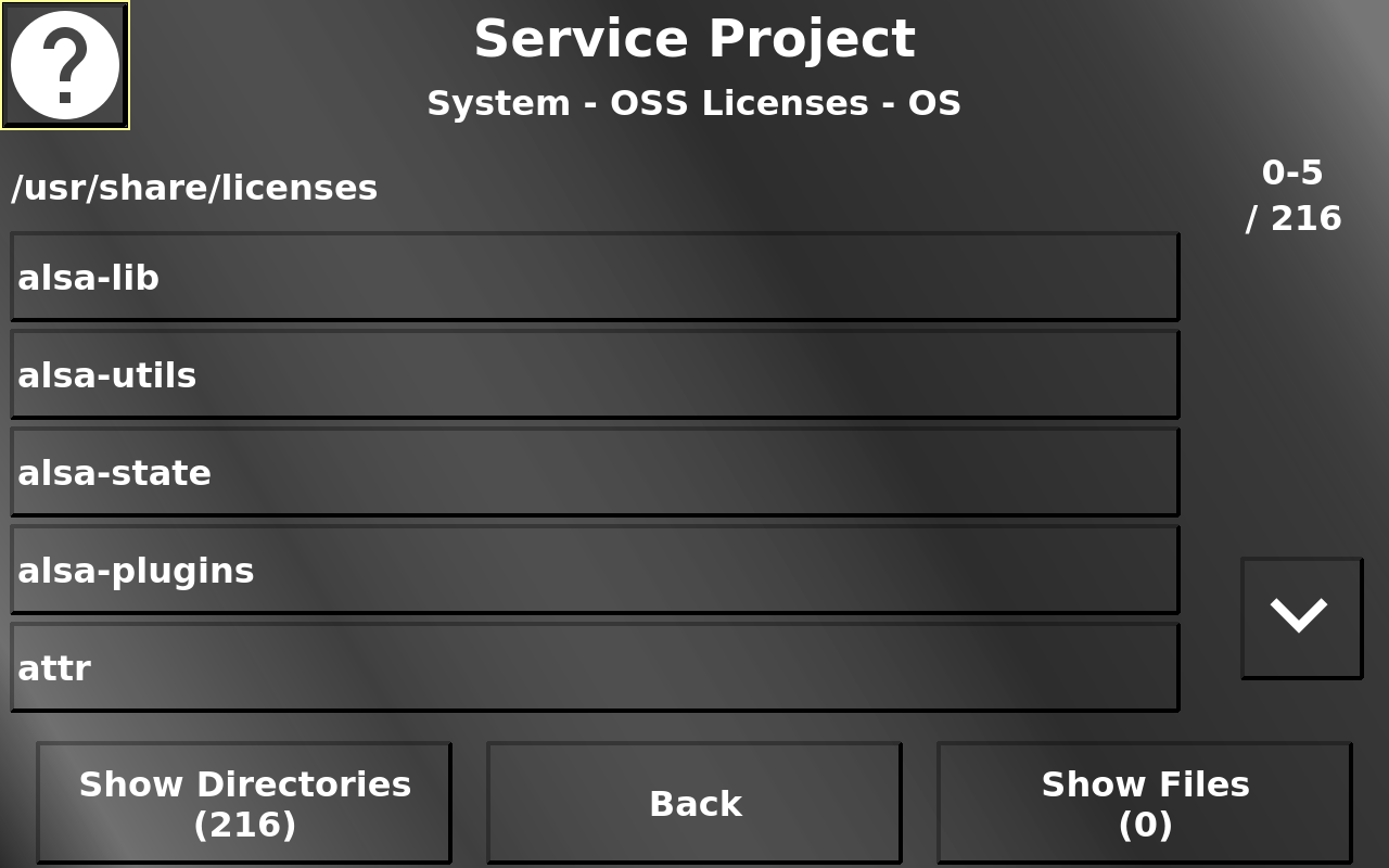
This page shows the open source licenses for the OS or for the PClient (depending on which button was pressed on the OSS licenses page). The view can be switched between directories and files.
For directories, a press of the according button will show the content of this directory. The current path is shown in the top of the screen. When directories are enterered, a "back" button will be displayed to go back up to the root of the OSS licenses folder. Both for files and directories, "up" and "down" buttons will be shown if more than 5 directories / files are present in the current directory.
For files, a button press will open an alarm with a preview of the file. The license text can be scrolled to see more content. Back returns to the OSS Licenses page.
Service Project -> System -> Watchdog
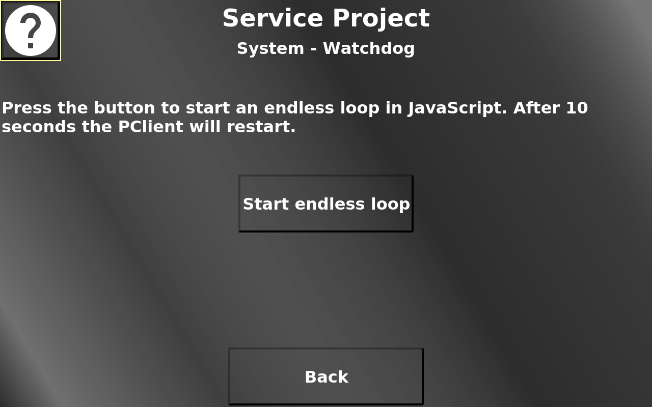
The PClient has an integrated watchdog that can be tested here. Pressing the "Start endless loop" button starts a JavaScript with an endless loop. Thus the PClient cannot continue its main loop. The Welcome Project is configured to restart the PClient after 10 seconds of being stuck. So 10 seconds after pressing the button the PClient will restart.
Service Project -> Sensors
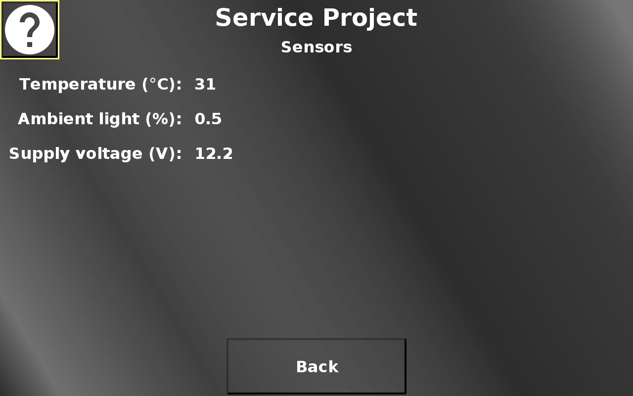
In this screen, the available hardware sensor values can be viewed. Back returns to the main menu.
Service Project -> Objects and Functions
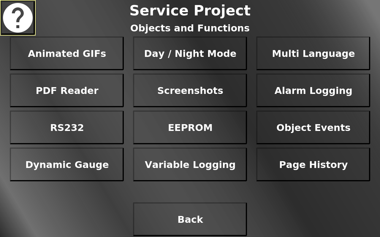
In this screen some functionalities of the OPUS Projektor and the PClient can be tested.
Service Project -> Objects and Functions -> Animated GIFs
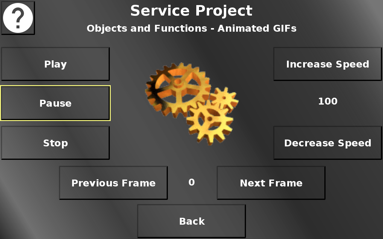
In this screen, an exemplary animated GIF file can be controlled.
Play starts the animation.
Pause pauses the animation (but stays at the current frame).
Stop stops the animation (and resets it to the first frame).
Increase speed increases the playing speed.
Decrease speed decreases the playing speed.
Back returns to the Objects and Functions menu.
Service Project -> Objects and Functions -> PDF Reader
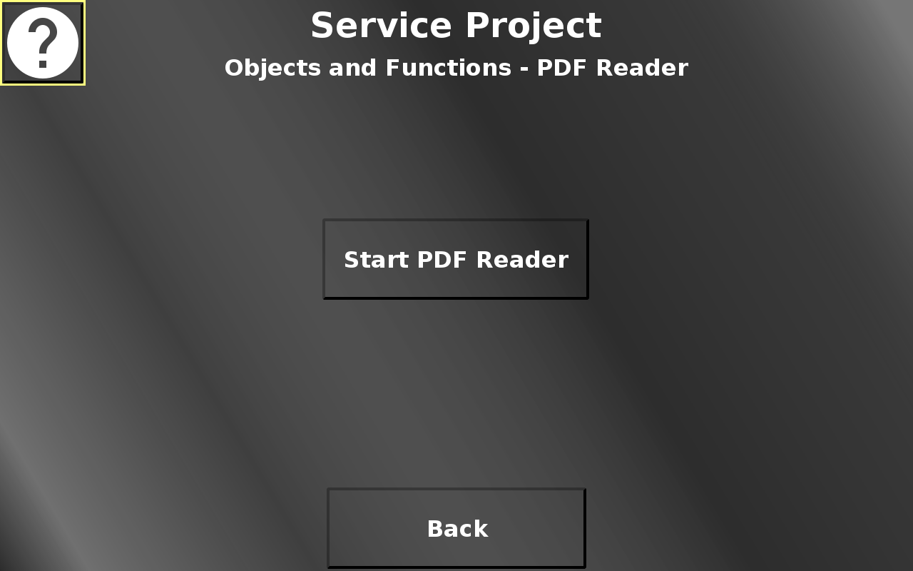
In this screen the PDF reader can be started with an exemplary PDF file.
Please note that it might take a while for the PDF reader to be started. Please be patient.
Please note that the PDF reader opens as a separate full screen application. Close it to go back to the PClient.
Back returns to the Objects and Functions menu.
Service Project -> Objects and Functions -> RS232 Setup Page
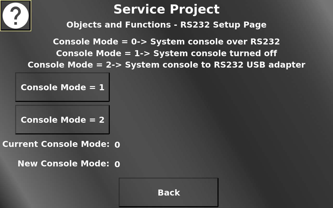
In this screen necessary settings to use the RS232 port for data communication can be made. By default, the RS232 port will be used by the device operating system console. To be able to use the RS232 port for data communication, the console mode needs to be set to 1 (system console off) or 2 (system console goes to the first USB-RS232 adapter (with USB side plugged into the device).
Please note that this screen is only displayed if the current console mode is 0.
The device needs to be restarted for this setting to be activated.
The current console mode and the new selected console mode is displayed below the two console mode buttons.
Once a new console mode is selected, a restart button is made visible.
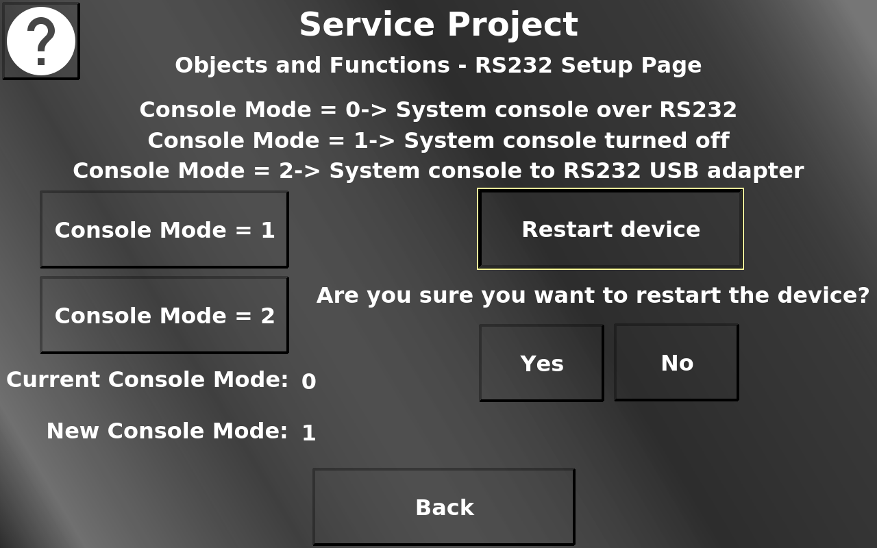
Yes restarts the device with the chosen console mode setting. No closes the dialog and resets the console mode back to 0. Back returns to the Objects and Functions menu.
Service Project -> Objects and Functions -> RS232 Data Page
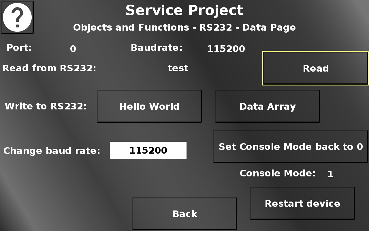
In this screen, RS232 data communication can be tested.
Please note that this screen is only shown if the console mode is 1 or 2 (see previous screens).
Read reads the RS232 buffer and displays the result (if it is text).
Hello World writes a "Hello World" to the RS232 port to be received by the other end.
Write Arrays writes a data array to the RS232 port to be received by the other end.
Set Console Mode back to 0 sets the console mode back to 0.
Restart device opens a confirmation dialog.
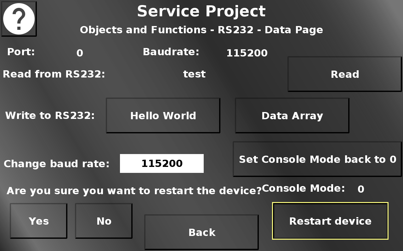
Yes restarts the device with the current console mode setting.
No closes the dialog and reverts the changed console mode setting.
Back returns to the Objects and Functions menu.
Service Project -> Objects and Functions -> Dynamic Gauge
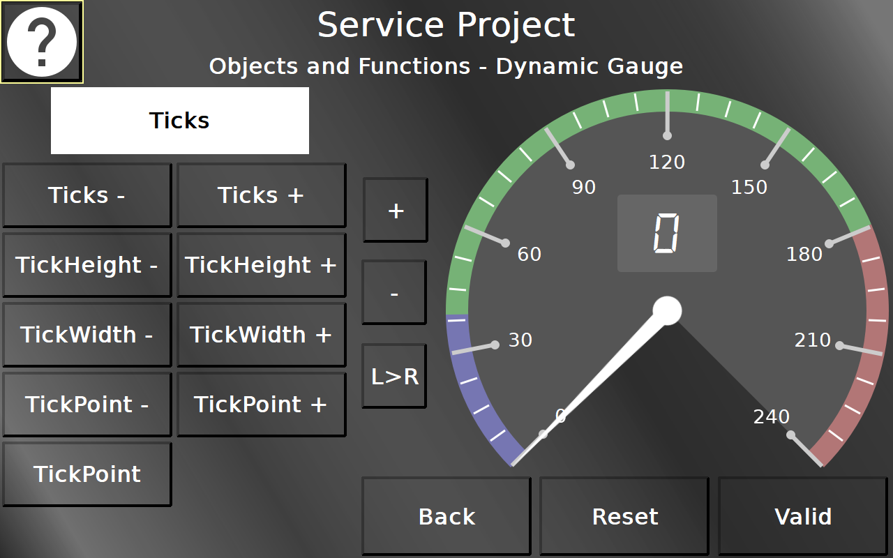
In this screen the dynamic possibilities of the Gauge object can be tested. The white list object contains 8 different categories of properties. The different buttons change the according properties of the gauge at run time.
Reset resets the object to the default setup.Valid switches between valid and invalid state of the variable connected to the gauge.
+ and - change the value of the connected variable. L>R switches the direction of the gauge.
Back returns to the Objects and Functions menu.
Service Project -> Objects and Functions -> Day / Night Mode
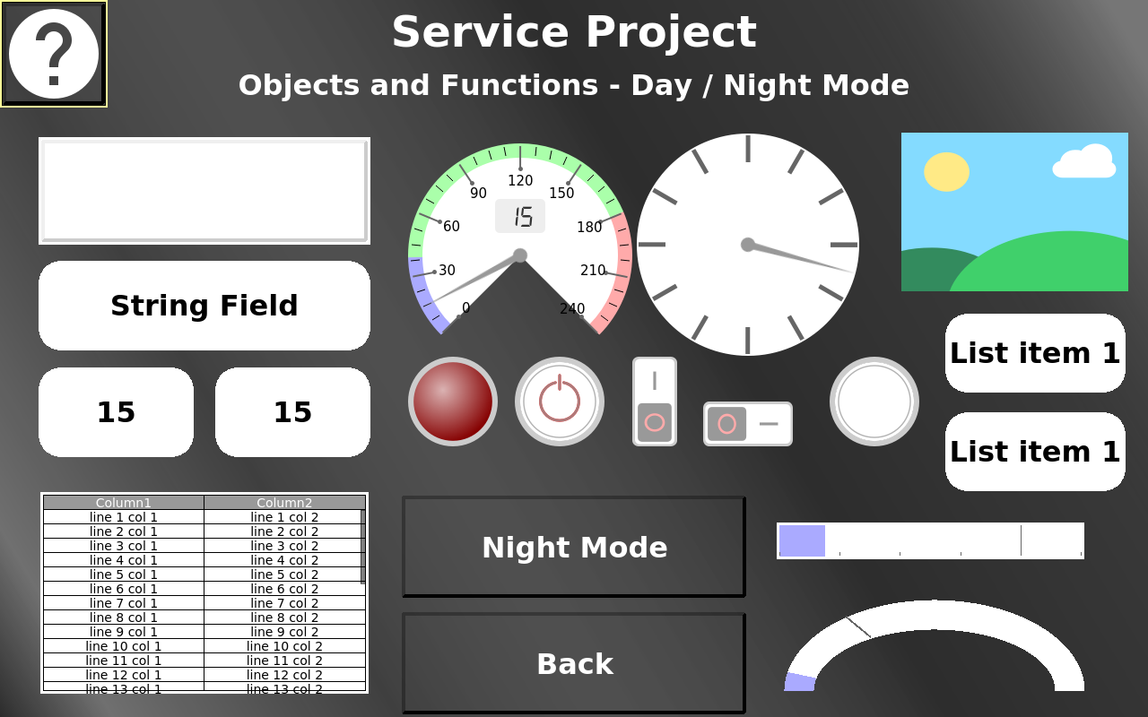
In this screen the day / night mode can be tested.
The Night Mode / Day Mode button switches all objects between their day mode / night mode theme.
The input objects can be tested, including the standard and touch input for the list object and Encoder and Virtual Keyboard editing for the Numeric Fields.
Back returns to the Objects and Functions menu.
Service Project -> Objects and Functions -> Screenshots
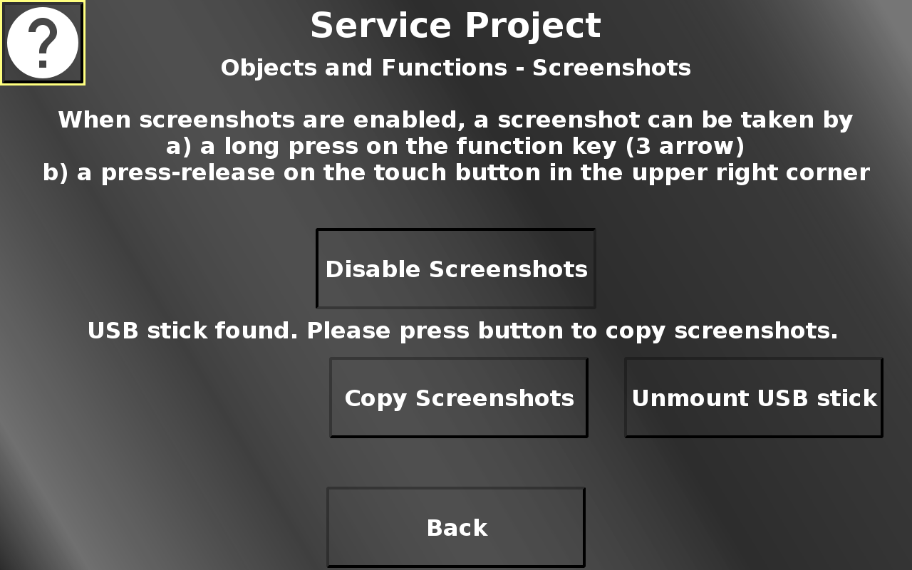
In this screen, screenshots can be enabled by pressing "Enable Screenshots". When screenshots are enabled, a screenshot can be taken on every page by either pressing the camera button in the upper right, or by long-pressing the 3 arrow key on the device. Screenshots will be stored on the file system. If a USB stick is plugged in and mounted, the screenshots can be copied to the USB stick by pressing "Copy Screenshots". The USB stick can be unmounted by pressing "Unmount USB stick". Back returns to the Objects and Functions menu.
Service Project -> Objects and Functions -> EEPROM
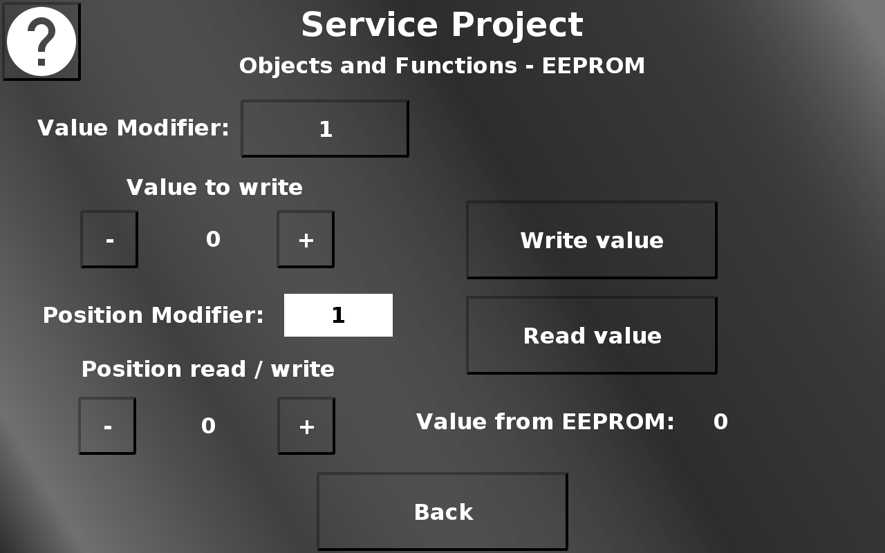
In this screen the EEPROM can be tested by writing to it and reading from it. The value that should be written into an EEPROM position can be set between 0 and 255 with the + and - buttons. They will increment and decrement either by 1 or 10, depending on the value modifier setting. Write value will write the currently set value to the currently set position. The position can be set between 0 and the maximum for the device with the + and - buttons. They will increment and decrement by the value chosen in the position modifier drop down. Read value will read the value from the currently set position and display it. Back returns to the Objects and Functions menu.
Please note that EEPROMs have limited write cycles, so avoid writing into the same position too many times without reason to do so.
Service Project -> Objects and Functions -> Variable Logging
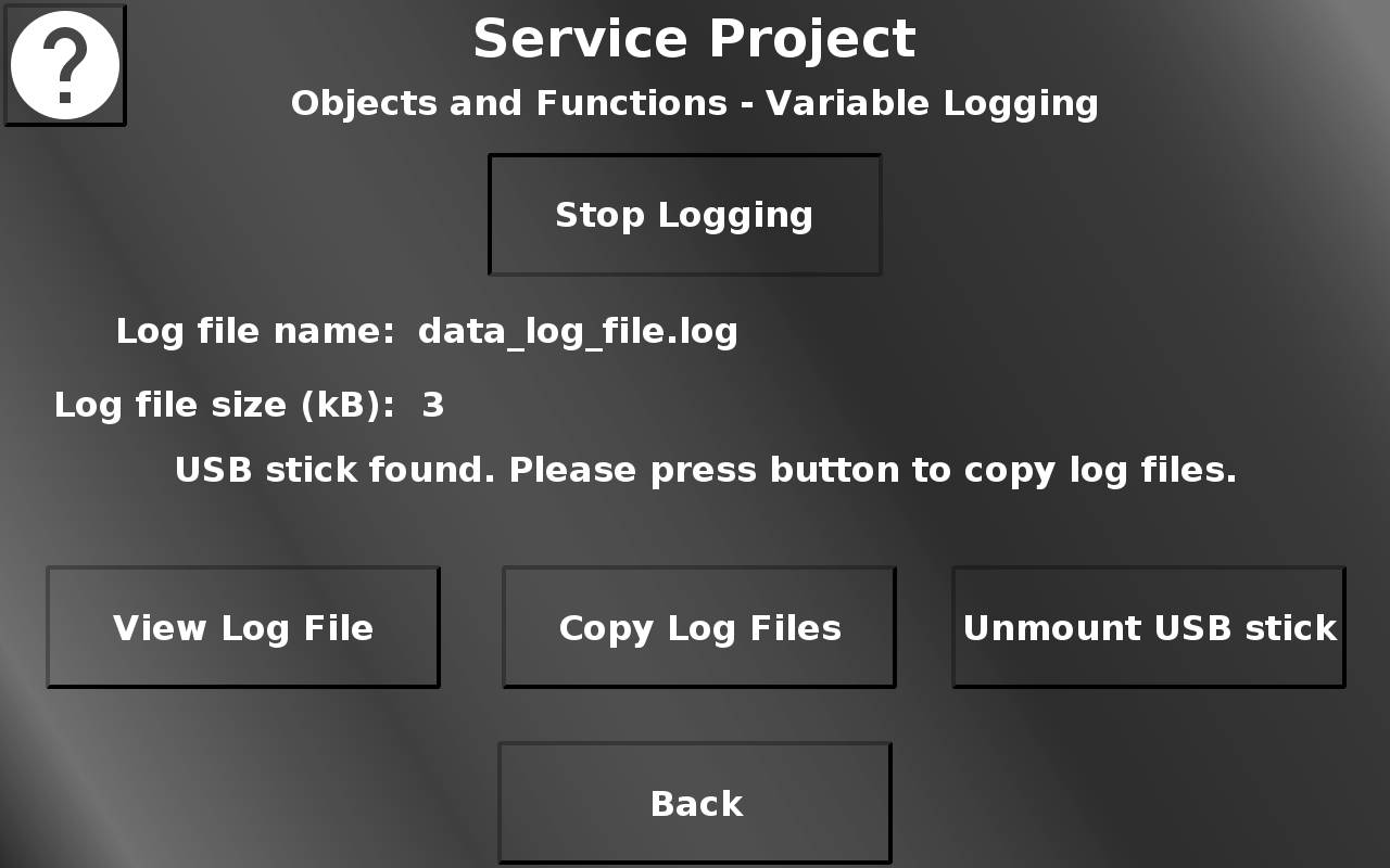
In this screen the variable logging functionality can be tested. Press Start Logging to start the variable logging. The logged variable is the RTC seconds variable, so there will be one event each second. The file can be viewed by pressing View Log File. This opens up an alarm showing the content of the file. Close the alarm by pressing Close. The Log File(s) can be copied to a connected USB stick by pressing Copy Log Files. Press Unmount USB stick to unmount the USB stick. Back returns to the Objects and Functions menu.
Service Project -> Objects and Functions -> Multi Language
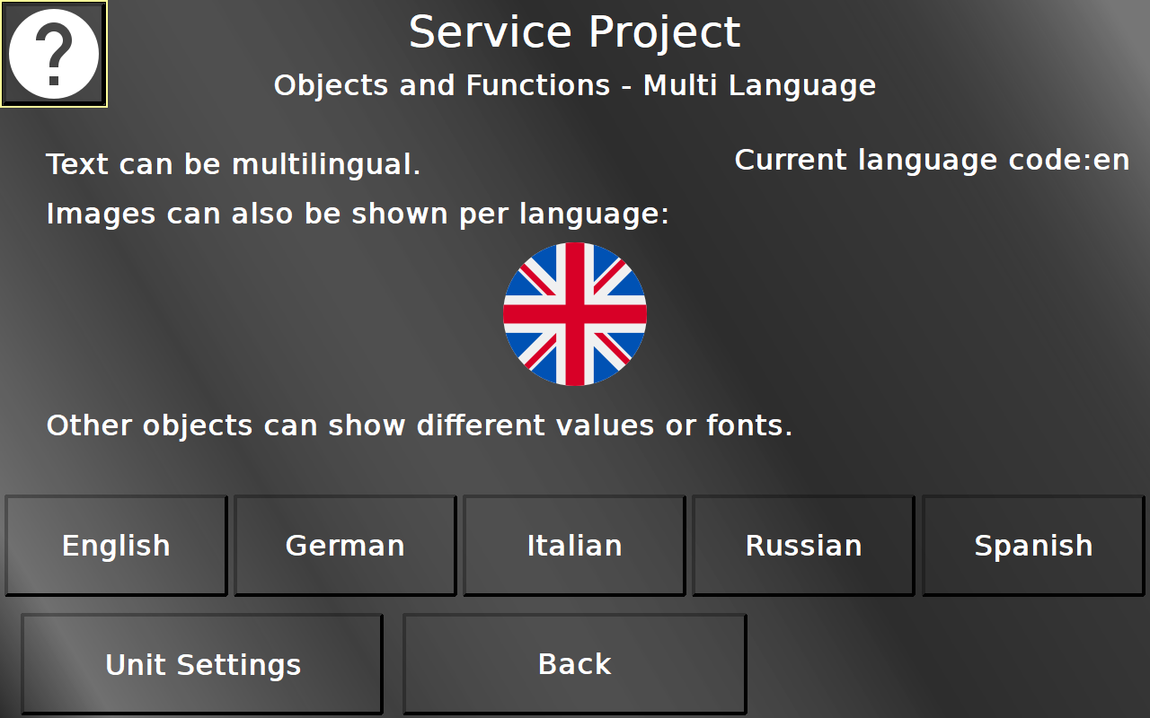
In this screen the multi language functionality can be tested. The five language buttons switch the texts and the image between the languages. Back returns to the Objects and Functions menu.
The used language flag icons were created by Freepik from www.flaticon.com. The Unit Settings button leads to the Unit Settings page. Back returns to the Objects and Functions menu.
Service Project -> Objects and Functions -> Multi Language -> Unit Settings
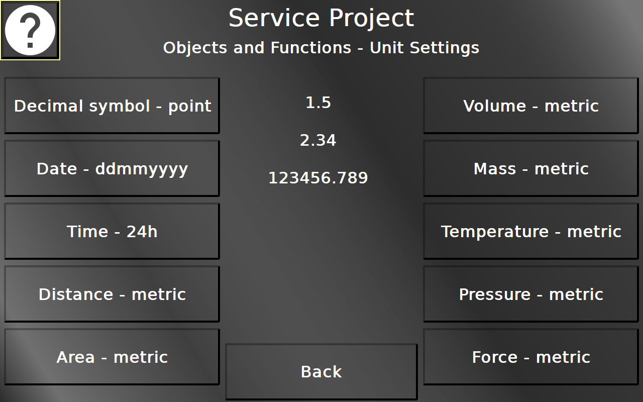
In this screen several unit settings can be tested. Each button changes the unit settings for the according topic. All settings are only for the displayed objects and will be reverted when leaving the page. Back returns to the Multi Language page.
Service Project -> Objects and Functions -> Alarm Logging
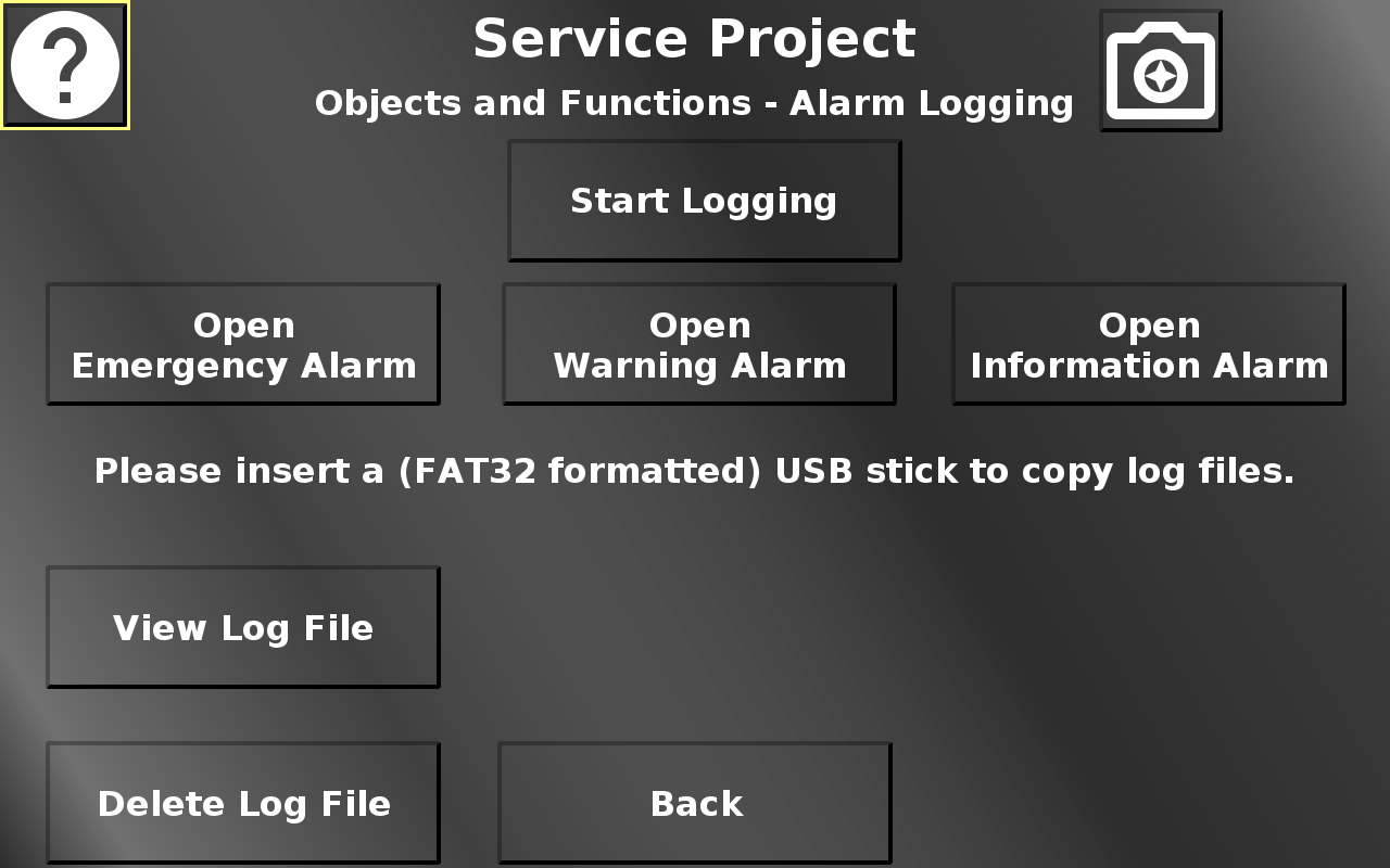
In this screen alarms and alarm logging can be tested. To enable alarm logging, press the Start Logging button. To stop it, press it again. The three Open ... Alarm buttons open an alarm from one of the categories Emergency, Warning or Information(al). From the opened alarm pop up, the alarms of the other two categories can be opened as well, to demonstrate the enqueuement and priority of the different alarm categories. View Log File opens an alarm that shows the newest entries in the alarm log file. Press Delete Log File to delete the current log file. If a USB stick is inserted, the alarm log file can be copied to the USB stick. The USB stick can also be unmounted.
Back returns to the Objects and Functions menu.
Service Project -> Objects and Functions -> Object Events
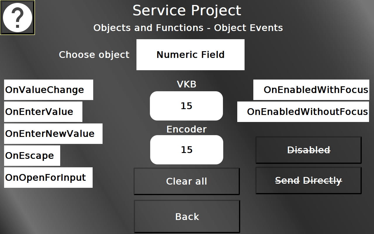
On this page most object events of all input objects can be tested. In the list object in the top an object type can be selected, from String Field, Numeric Field, Button, Table, List, Meter, Gauge, Arched Bargraph, Linear Bargraph.
For the selected object type, the available events are listed on the left and right of the object in the center. Use the object and/or change its value to activate the events. An activated event will get a green background.
With Clear all, the event backgrounds can be reverted to white.
With the disabled button the object under test can be disabled. That will deactivate it as an input, and it will be shown grayed out and strike through.
With the Send Directly button the behavior of the according object can be changed. With send directly, each encoder rotation will directly invoke a value change. Without it, only when confirming the value, it will actually be changed.
Back returns to the Objects and Functions menu.
Service Project -> Objects and Functions -> Page History
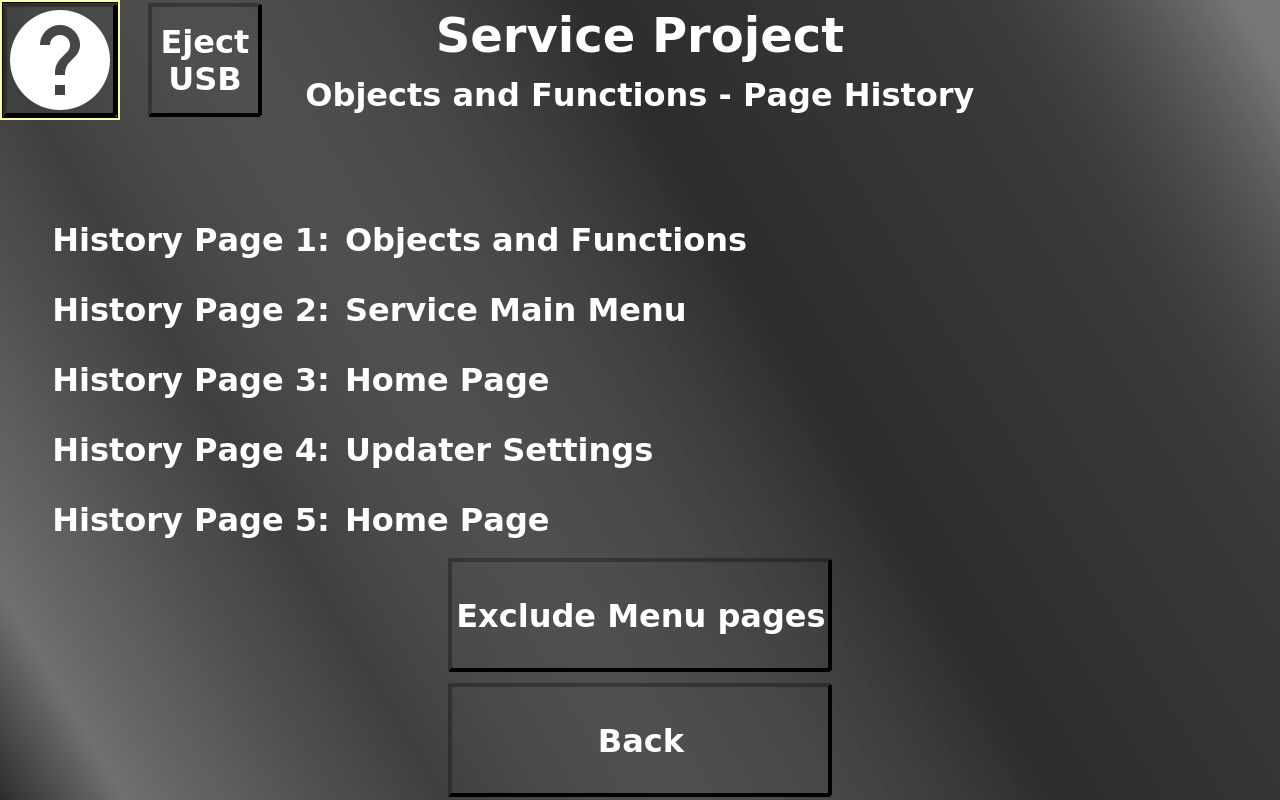
In screen the last 5 pages that were visited are shown. To de-clutter the list, menu pages can be excluded from the history list. Note that this will change the behavior of the escape button.
Service Project -> Info to USB
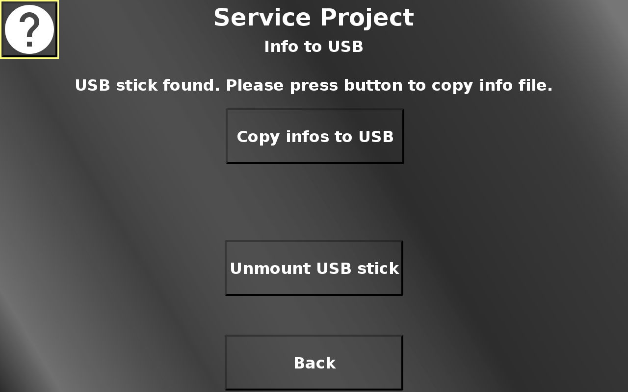
In this screen a file with information about the device can be written to a connected USB stick for analysis or to be sent to technical support.
Copy infos to USB creates the info file and puts it on the USB stick. Please note that this button is only shown if a valid USB stick is connected.
This is an exemplary content of an info file:
Device Info
Article number: OPUSA8SN1CANB000
Serial number: 1611001AA
Device type: 12.1" Standard Basic
OS version: 4.1.15-egspro-2.3.2-1
PClient version: 2020.4.0.2
Project version: 0.1
Operating time: 2 d, 7 h, 12 m
System Uptime: 0 h, 6 m, 28 s
Date / Time: 2020/2/28 - 14/16/18
System memory: 1192.784 MB / 1312.900 MB
Device temperature: 41.2 °C
Device voltage: 24.4 V
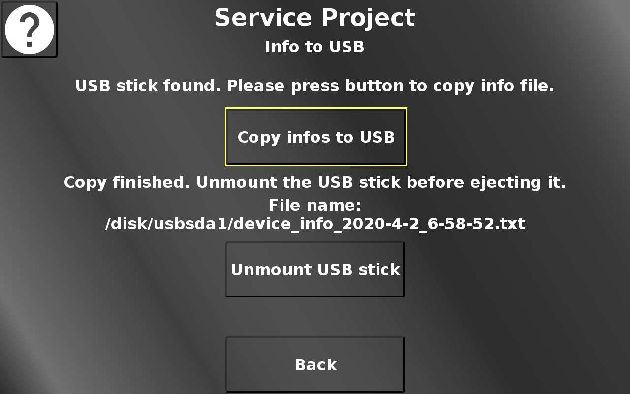
After copying, the file name of the created file will be shown.
Unmount USB stick unmounts the USB stick so it can be ejected from the device.
Please note that until the USB stick is mounted, the file might not be finalized on the USB stick. Ejecting the USB stick before unmounting means a probable loss of the info file.
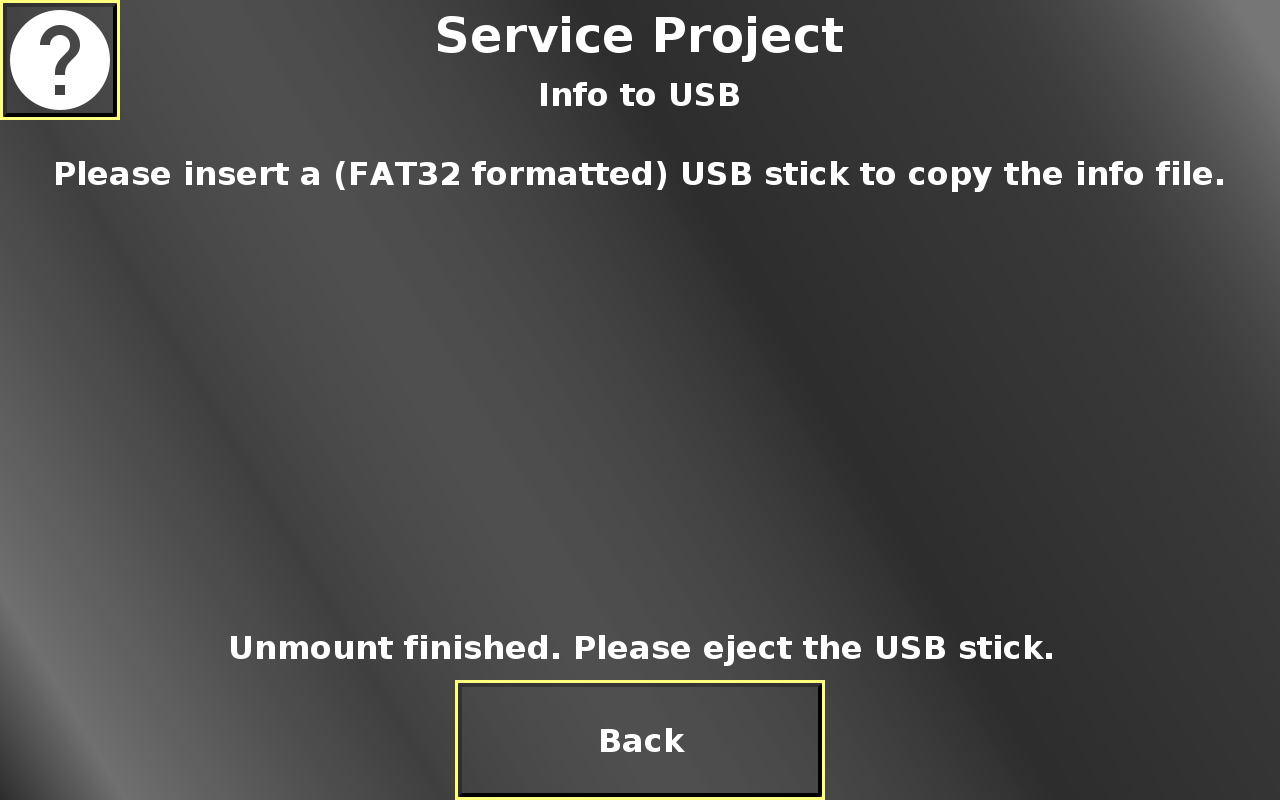
When the USB stick is successfully unmounted, an information will be displayed on the screen that the stick can be ejected.
Back returns to the main menu.
Service Project -> CAN
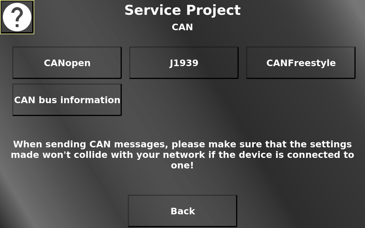
In this screen the different CAN protocols can be selected for some tests.
Please note that if the device is connected to a CAN network, it is your responsibility that the messages created in these tests don't collide with the CAN network.
Back returns to the main menu.
Service Project -> CAN -> CANopen
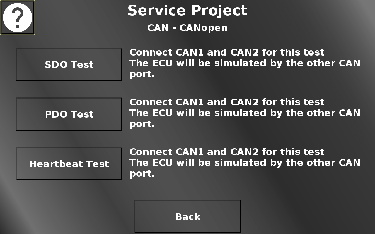
In this screen the SDO and the PDO Test can be selected. Please note that for these tests to work, the device ports CAN 1 and CAN 2 need to be connected.
Back returns to the CAN menu.
Service Project -> CAN -> CANopen -> SDO Test
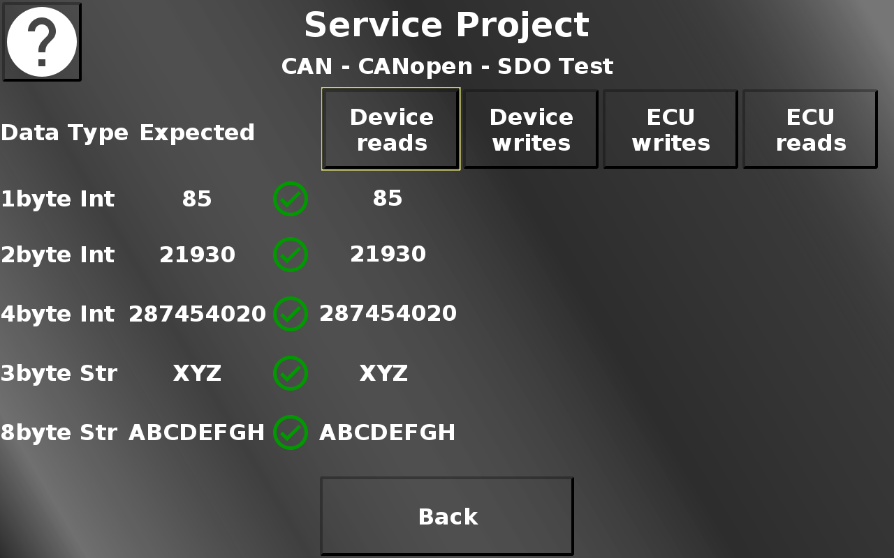
In this screen different SDO functionalities can be tested.
Device reads means that the OPUS device will ask the ECU (aka CAN port 2) for some data values. If the communication is successful, the values in the Expected column should be the same as in the ask ECU column. The check boxes show if the values match. Create a CAN trace to see the communication process.
Device writes means that the OPUS device will send a write request to some variables belonging to the ECU (aka CAN port 2). If the communication is successful, the values in the Expected column should be the same as in the Device writes column. The check boxes show if the values match. Create a CAN trace to see the communication process.
ECU writes means that the ECU (aka CAN port 2) writes some variables in the OPUS device. If the communication is successful, the values in the Expected column should be the same as in the ask ECU writes. The check boxes show if the values match. Create a CAN trace to see the communication process.
ECU reads means that the ECU (aka CAN port 2) reads some variables from the OPUS device. If the communication is successful, the values in the Expected column should be the same as in the ECU reads column. The check boxes show if the values match. Create a CAN trace to see the communication process.
Back returns to the CANopen menu.
Service Project -> CAN -> CANopen -> PDO Test
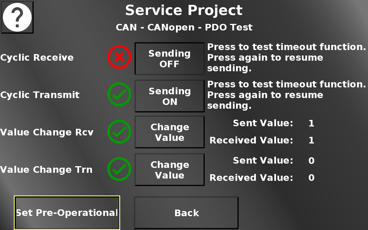
In this screen some PDO functionalities can be tested. For the PDO communcation to start, the device first needs to be set into operational mode with the button in the bottom left.
The first two indicators show a green check mark if the cyclic receive and transmit communication work correctly. You can disable the sending of the appropriate message with the according button. This should make the red X appear. Note that the ECU is simulated with CANFreestyle mappings on CAN port 2.
The second two indicators show a green check mark if the sent value and the received value of a CANopen Receive(Rcv) and Transmit (Trn) mapping are identical.
Press the buttons to change the sent value. The received value should change to the same almost instantly. Only very quick taps on these buttons should make the red X appear.
Initially, the received values are set to invalid, so the red X will appear for both values. Once this communication was established, the green check mark will be displayed as long as the values are the same, even if the device is set to pre-operational (i.e. it cannot send or receive messages). Press the buttons to change the sent value and the red X should appear.
Also note that once the device is back to operational, only the Transmit (Trn) value might automatically update. This is a property of the CANopen standard, when a device first goes into operational mode, it will once send all transmit mappings with their current values. The Receive (Rcv) value is being sent by a CANFreestyle mapping on CAN port 2 which does not have such a feature. Press the Change Value button, then the received value should also update and the green check mark appears.
Back returns to the CANopen menu.
Service Project -> CAN -> CANopen -> Heartbeat Test
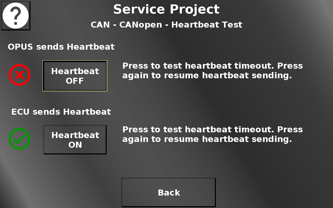
In this screen the CANopen heartbeat functionality can be tested.
When entering this page, the CANopen stack on the device will produce a heartbeat message every 100 ms (ID 0x701) on CAN bus 1. A CANFreestyle receive message on CAN bus 2 checks for this message and shows the red X if the heartbeat isn't received for more than 200 ms. If the heartbeat is received again, the green check mark is displayed.
Simulating an ECU, a CANFreestyle transmit message on CAN bus 2 will be sent to imitate a heartbeat message from the ECU every 100 ms. The CANopen stack on CAN bus 1 will evaluate the message. If it hasn't been received for 200 ms, the red X will be shown. If the heartbeat message is received again, the green check mark is displayed.
Back returns to the CANopen menu.
Service Project -> CAN -> J1939
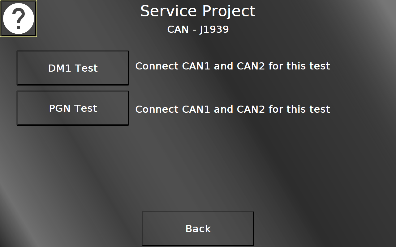
In this screen the test pages for DM1 and PGNs can be opened. Please note that for these tests to work, the device ports CAN 1 and CAN 2 need to be connected.
Back returns to the CAN menu.
Service Project -> CAN -> J1939 -> DM1
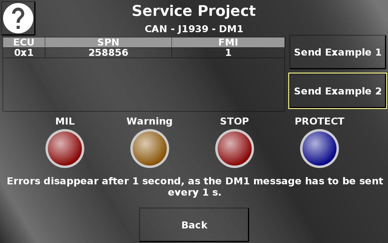
In this screen two DM1 tests can be performed.
Send Example 1 will send an error to the OPUS device and let one lamp blink slowly.
Send Example 2 will send a different error to the OPUS device and let all lamps blink fast.
Please note that the errors will disappear after 1 second. DM1 messages have to be sent every 1 s which is why the buffer is automatically cleared after 1 second.
Back returns to the J1939 menu.
Service Project -> CAN -> J1939 -> PGN Test
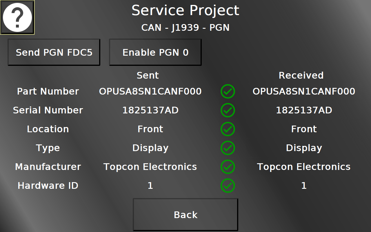
On this screen, two PGNs can be tested. PGN FDC5 contains some device information. With Send PGN FDC5 the PGN is sent from CAN bus 1 to 2 and the received values are compared to the actual values on the left. If they are correct, green check marks will be displayed. If they are not, a red cross will be displayed instead. The values for Location, Type, Manufacturer and Hardware ID can be edited.
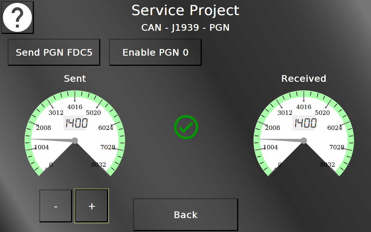
Pressing Enable PGN 0 starts the periodic transfer of PGN 0, usually used to transfer the target RPM. The gauge on the left side shows the value that is transferred, the gauge on the right shows the received value. With the plus / minus buttons the value can be changed.
If the values are identical, a green check mark will be displayed. If they are not, a red cross will be displayed instead.
Back returns to the J1939 menu.
Service Project -> CAN -> CANFreestyle
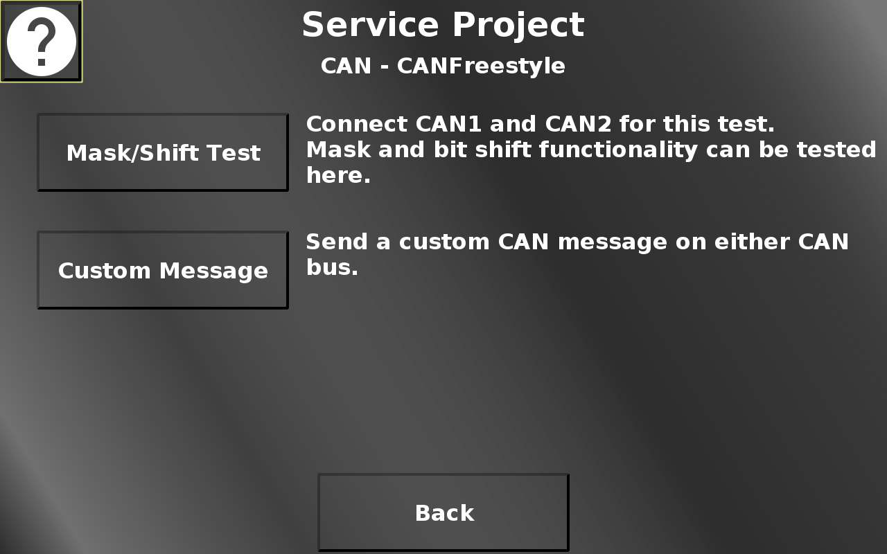
In this screen the mask, bit shift, scaling and offset test page and a page to send a custom CAN message can be opened. Back returns to the CAN menu.
Service Project -> CAN -> CANFreestyle -> Mask / Shift Test
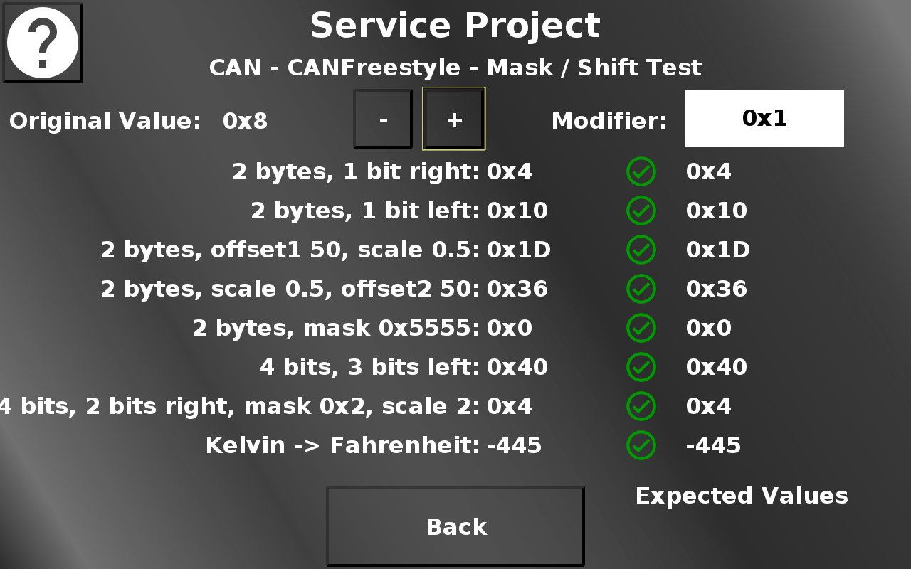
On this page, different masking, bit shift, scaling and offset functionalities can be tested. For this test to work, CAN1 and CAN2 have to be connected.
In the top the original value can be changed (shown in hexadecimal). The Modifier dropdown chooses the modifier by which plus and minus buttons change the value. In each line below some modifications of the original value are configured in the CAN receive mapping. The left value shows the modified value. The right value shows the same modification done in JavaScript. The two value are compared every time the value is changed and the CAN message is sent again. If the values match, a green check mark is shown. If the values don't match, a red X is shown.
Back returns to the CAN Freestyle menu.
Service Project -> CAN -> CANFreestyle -> Custom CAN Message
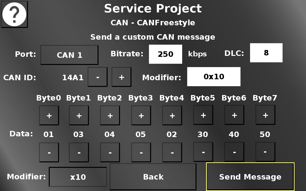
In this screen a custom CAN message can be set up which will be sent to the chosen CAN bus.
Please note that creating the "wrong" message can be dangerous for the system the device is connected to.
The CAN 1 / CAN 2 button chooses over which CAN bus the message should be sent.
In the Bitrate dropdown the bitrate can be chosen with which the message should be sent.
In the DLC drowpdown the length of the message can be chosen. Values from 0 to 8 are possible.
The CAN ID - (minus) and + (plus) buttons change the value of the CAN ID of the message.
The Modifier dropdown chooses the modifier by which the CAN ID will be changed. In the displayed setup, a press of the + button will change the CAN ID from 0x1A0 to 0x1B0.
The + and - buttons of the data bytes change the data value of each byte.
The segments for the data bytes will be made invisible depending on the DLC selection.
The modifier button in the bottom switches between 0x1 and 0x10. The - / + buttons for the data bytes modify the value by the selected modifer.
Send Message sends the CAN message with the chosen settings.
Back returns to the CAN menu.
Service Project -> CAN -> Can bus information
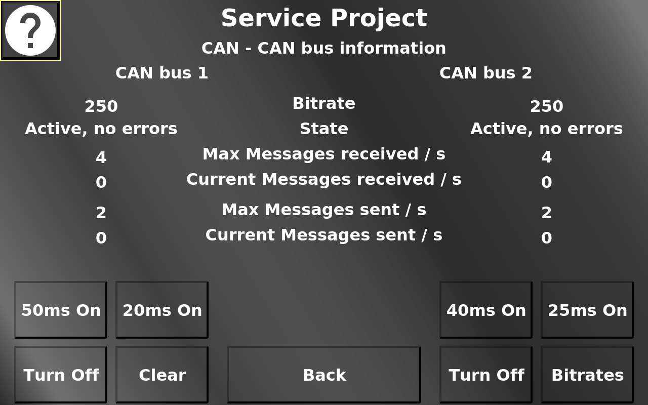
On this screen some information about the CAN ports can be seen. To change the current and maximum messages, two CAN messages can be activated for each CAN port. The maximum values can be reset by pressing the Clear button. The Turn Off buttons turn the appropriate CAN bus of to simulate error cases. The Bitrates button opens an alarm where the bit rates of each CAN bus can be changed to simulate errors.
On devices with 4 CAN buses, an additional button CAN 3/4 is displayed. That page offers an identical information about CAN busses 3 and 4, but has no possibility to simulate CAN traffic or errors, that has to be done externally.
Back returns to the CAN menu.
Service Project -> LED / Backlights
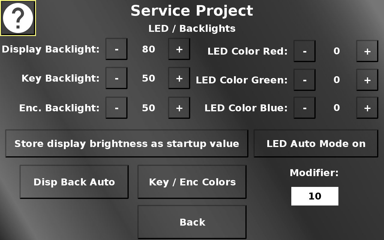
The LED / Backlights screen allows changing the values for display, key, encoder backlight and the multicolor LED.
The - (minus) and + (plus) buttons change the according value. The amount that the current value is modified by, can be chosen with the Modifer dropdown.
Store display brightness as startup value changes the startup display brightness (i.e. the screen brightness when the device is powered on until the application setting sets in).
LED Auto Mode on starts gradual color changes for the multi color led.
Disp Back Auto opens the automatic backlight setup screen.
Key / Enc Colors opens the screen for key and encoder backlight colors.
Back returns to the main menu.
Service Project -> LED / Backlights -> Display Backlight Auto Mode
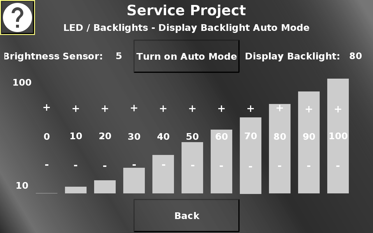
In this screen the automatic backlight control can be activated / deactivated.
Additionally, the backlight curve for the different brightness sensor values can be adjusted.
The first bar sets the brightness of the screen for an ambient brightness of 0 to 10 %.
The second bar sets the brightness of the screen for an ambient brightness of 10 to 20 %, and so on.
The - (minus) and + (plus) sections decrease / increase the brightness value for the according ambient brightness.
Back returns to the LED / Backlight menu.
Service Project -> LED / Backlights -> Keyboard / Encoder Colors
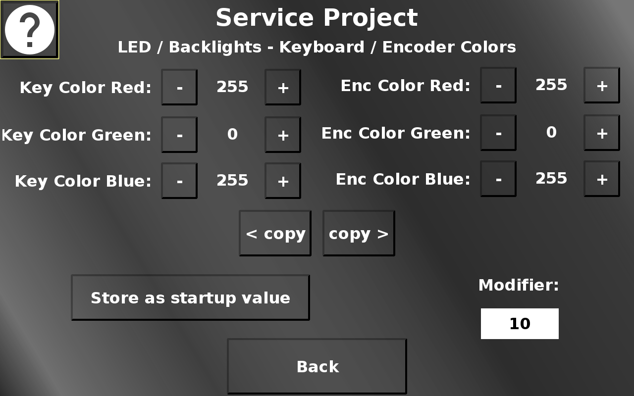
In this screen the colors for the key backlight and the encoder backlight can be adjusted (only available on certain devices).
The - (minus) and + (plus) buttons change the according value. The amount that the current value is modified by, can be chosen with the Modifer dropdown.
Store as startup value will set the backlight color that keys and encoder will have at startup until the application setting sets in.
The copy > and < buttons will duplicate the key color values to the encoder values and vice versa.
Back returns to the LED / Backlight menu.
Service Project -> Inputs / Outputs
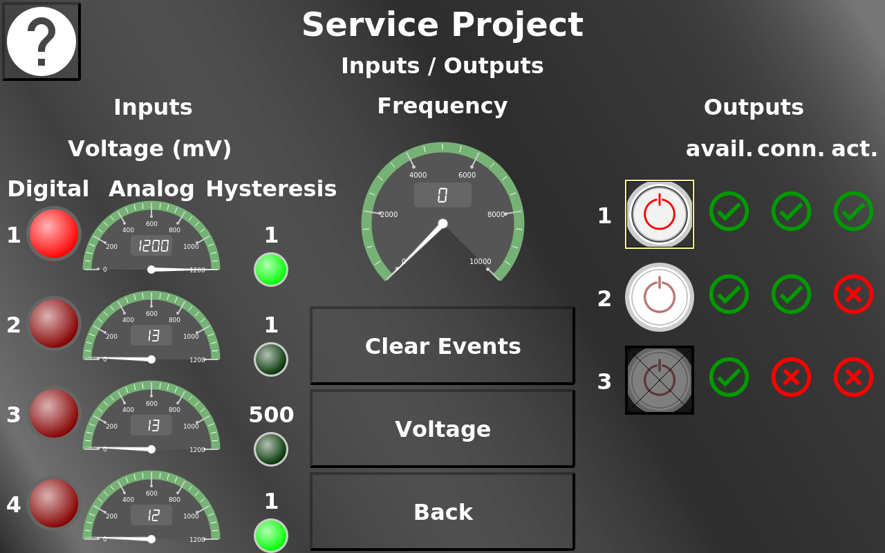
In this screen the analog / digital / current / frequency (where available) inputs can be viewed and the digital outputs can be set and their status can be viewed.
The Power Buttons for outputs 1 to 3 are inputs and can be activated / deactivated. This activates the according output.
The three symbols next to the buttons show the status of the according output. The first one (avail. for available) shows if the output is available on the device. The second one (conn. for connected) shows if the output is connected properly. The third one (act. for active) shows if the output is switched to active.
With the Voltage button the inputs can be switched between voltage and current inputs. The Hysteresis values can be edited to change the voltage / current difference that is needed to activate an event for each input variable. If an event occurs, the green lamps below the hysteresis values are lit up. Clear Events resets these event lamps.
Please refer to the how-to on digital outputs.
Back returns to the main menu.
Service Project -> Cameras
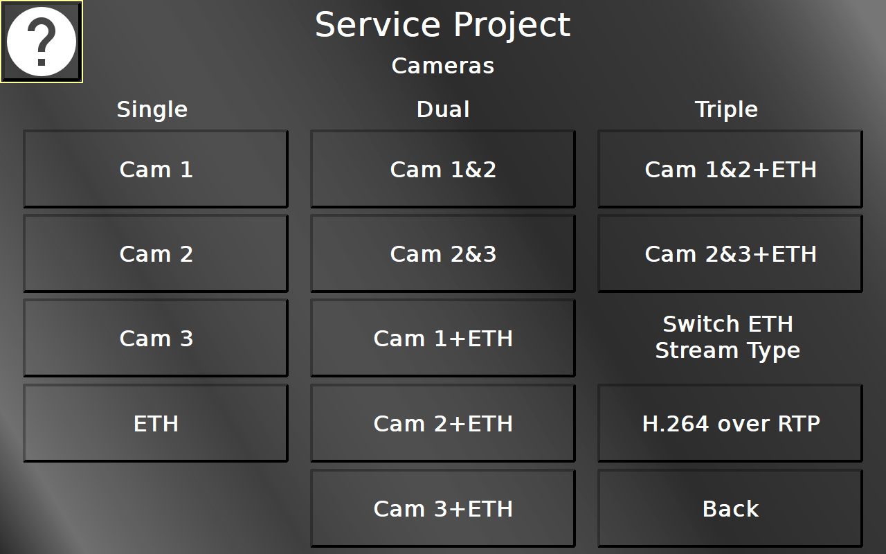
In this screen different camera screens can be chosen. Please note that only the available screens should be opened.
With the Switch ETH Stream Type button the Ethernet Camera input can be switched between H.264 over RTP / UDP, MJPEG over RTP / UDP and H.264 over RTSP protocols.
Back returns to the main menu.
Service Project -> Cameras -> Single Camera Pages
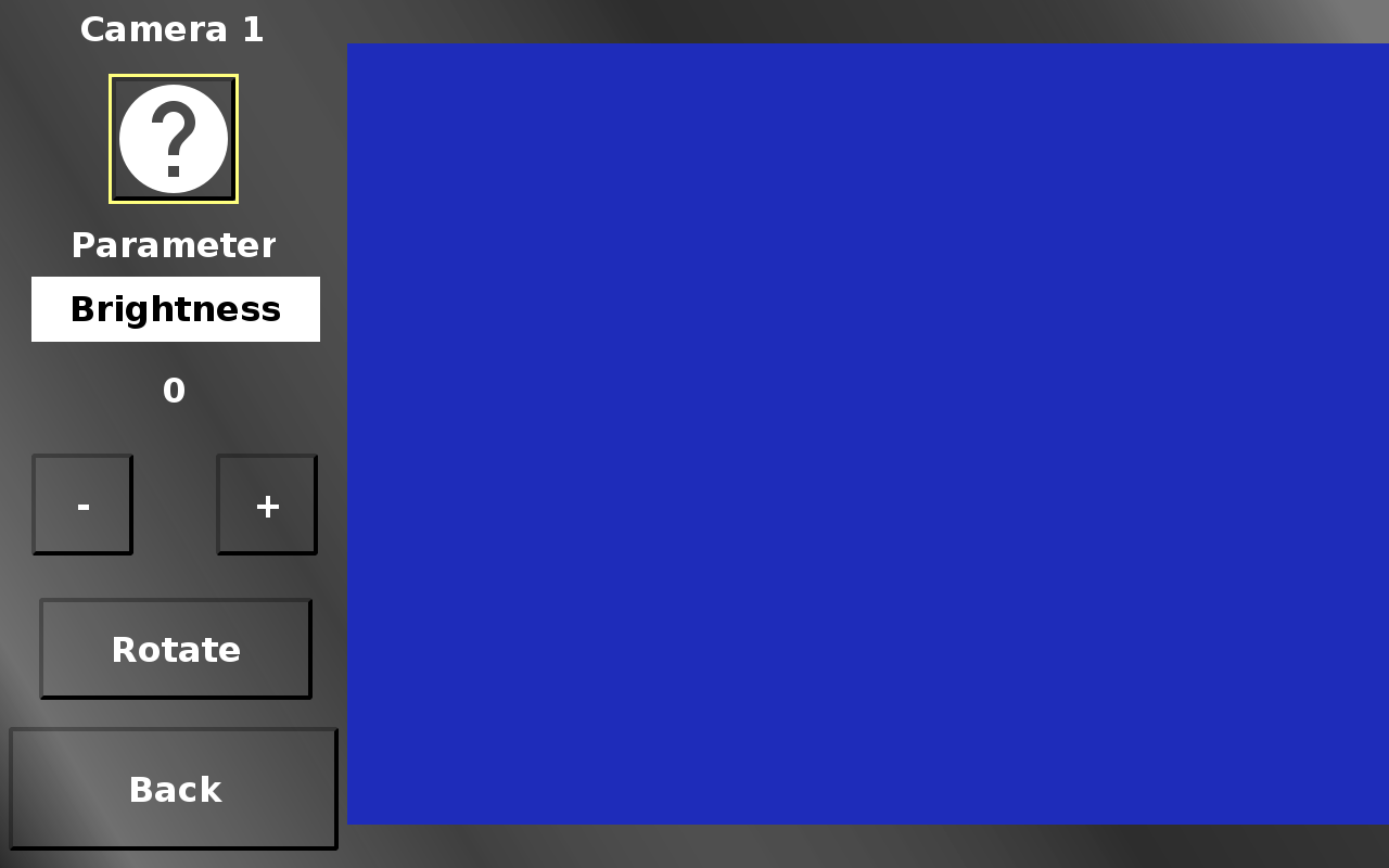
The parameter drop down in the single camera view screens chooses between the available camera image manipulations (brightness, contrast, saturation, height, width, rotation, mirror, x-position, y-position).
The - (minus) and + (plus) buttons change the according value.
Rotate rotates the image in steps of 90 degrees. This will set a combination of rotation and mirror values.
Back returns to the camera main menu.
Service Project -> Cameras -> Ethernet Camera (H.264 over RTP)
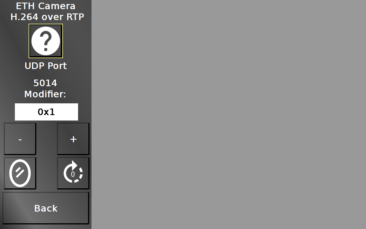
In this screen an Ethernet camera stream can be viewed. Note that only RTP over UDP is supported with the selection of H.264 over RTP in the main camera screen.
The UDP port can be set with the - (minus) and + (plus) buttons. The Modifier dropdown chooses the modify value.
The mirror button switches between not mirrored, horizontally mirrored, vertically mirrored and mirrored in both directions.
The rotation button switches between 0 °, 90 °, 180 ° and 270 °.
Back returns to the camera main menu.
Service Project -> Cameras -> Ethernet Camera (H.264 over RTSP)
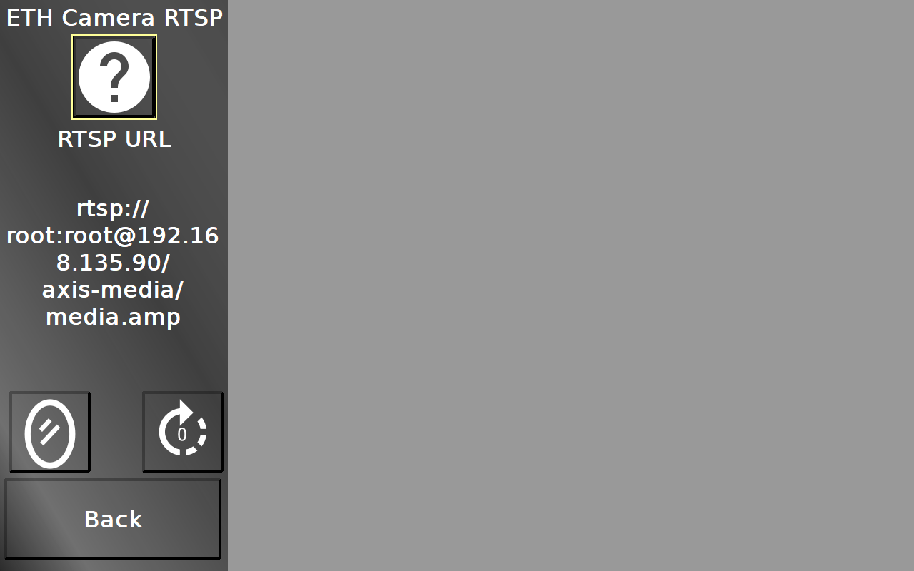
In this screen an Ethernet camera stream can be viewed. Note that only H.264 over RTSP / UDP is supported with the selection of RTSP protocol in the main camera screen.
The RTSP address can be set by selecting the String Field.
The mirror button switches between not mirrored, horizontally mirrored, vertically mirrored and mirrored in both directions.
The rotation button switches between 0 °, 90 °, 180 ° and 270 °.
Back returns to the camera main menu.
Service Project -> Cameras -> Ethernet Camera (MJPEG over RTP)
In this screen an Ethernet camera stream can be viewed. Note that only MJPEG over RTP / UDP is supported with the selection of RTSP protocol in the main camera screen.
The UDP port can be set with the - (minus) and + (plus) buttons. The Modifier dropdown chooses the modify value.
The mirror button switches between not mirrored, horizontally mirrored, vertically mirrored and mirrored in both directions.
The rotation button switches between 0 °, 90 °, 180 ° and 270 °.
Back returns to the camera main menu.
The other pages in the camera menu can show different multi camera settings. Note that not all combinations work with all device types. The combinations that are not possible, should be shown grayed out.
Service Project -> Clock
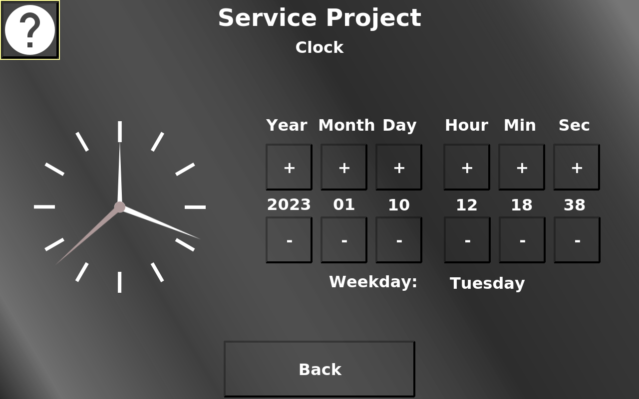
In this screen the date and time can be set. The - (minus) and + (plus) buttons change the according value.
The week day will be calculated automatically.
Back returns to the main menu.
Service Project -> Keys
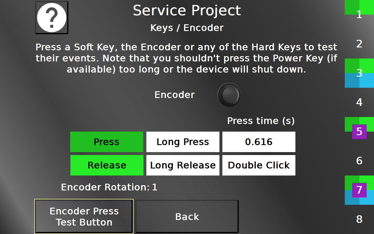
In this screen the soft- and hard keys as well as the encoder can be tested.
For the soft keys, both the actual physical key and the according touch region can be used to test.
For each event, the according field will be colored (Press - dark green, Release - light green, Long Press - dark blue, Long Release - light blue, Double Click - purple).
The background of the soft key touch regions will be colored in the same way when the according events are executed.
The pressed object will also be displayed in the center.
Additionally, the press time will be displayed for the last / current key being pressed.
The rotation of the Encoder is displayed in the Numeric Field in the bottom. The Encoder Test button below that does nothing, it can be used to test the press and release events of the encoder without executing any unwanted action.
The event fields and keys are cleared when re-entering the page.
Back returns to the main menu.
Service Project -> Touch
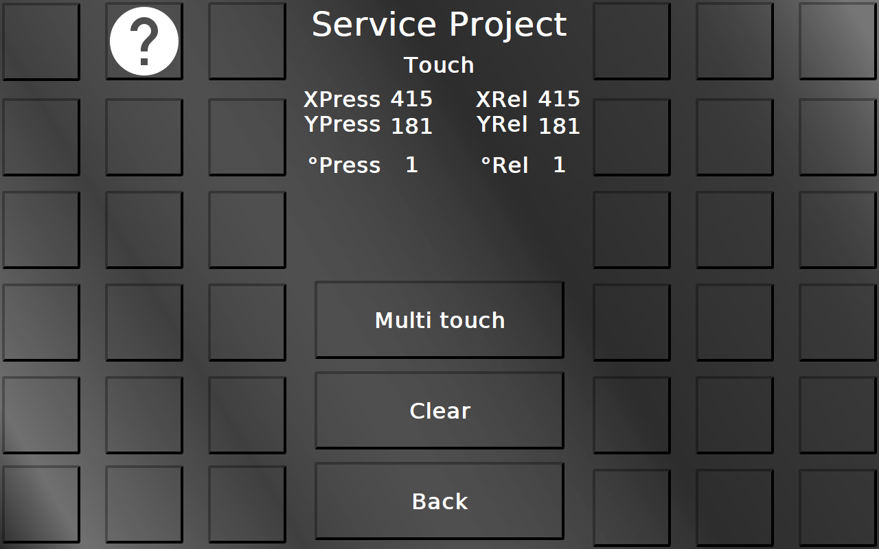
In this screen the touch input can be tested. Each squared button will be colored green if it has been touched, so a well-working screen should be able to color all buttons, and a button should only be colored green if it actually has been touched.
Additionally, the touch coordinates for X and Y both for pressing and releasing are displayed, as well as a counter number for the presses and releases of the touch.
With the button Touch calibration the touch screen calibration can be started. 5 cross hairs will appear one after another (top left, top right, bottom right, bottom left, center). Press the cross hairs to calibrate the screen.
Please note that the PClient stays on during this operation, so the cross hairs will be painted over this screen.
Please note that the calibration button is available only for resistive touch screens. Devices with capacitive touch screens do not need a calibration.
The button Multi touch leads to the multi touch test page. Please note that the multi touch functionality is not available on OPUS A3 and OPUS A6 G1.
Back returns to the main menu.
Service Project -> Touch -> Multi Touch
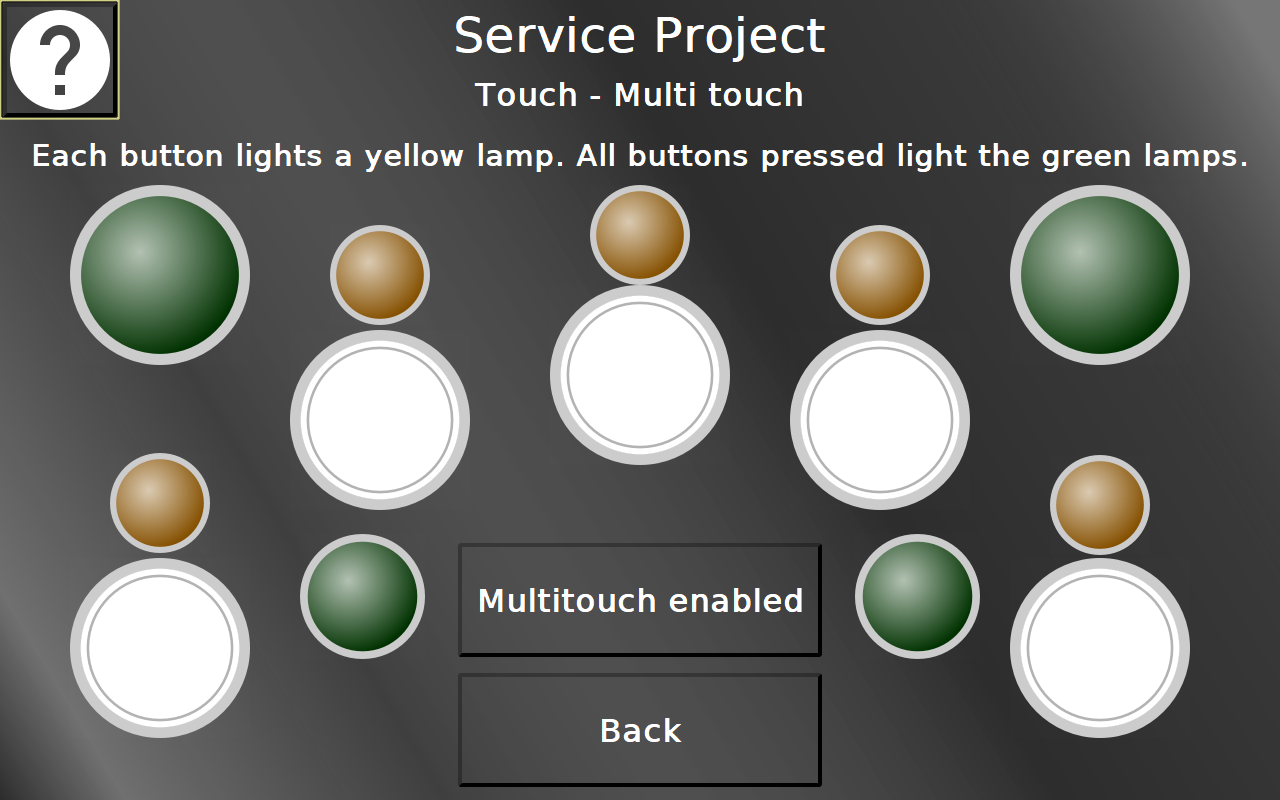
In this page the multi touch functionality can be tested. Depending on the capabilities of the hardware, 2 or 5 buttons, each with a lamp, will be displayed.
Each button lights up the according lamp. If all buttons are pressed at the same time, the green lamp lights up.
With the multi touch button the multi touch functionality can be disabled. After that the touch screen should only react upon the first finger press.
Back returns to the main menu.
Service Project -> Audio / Video
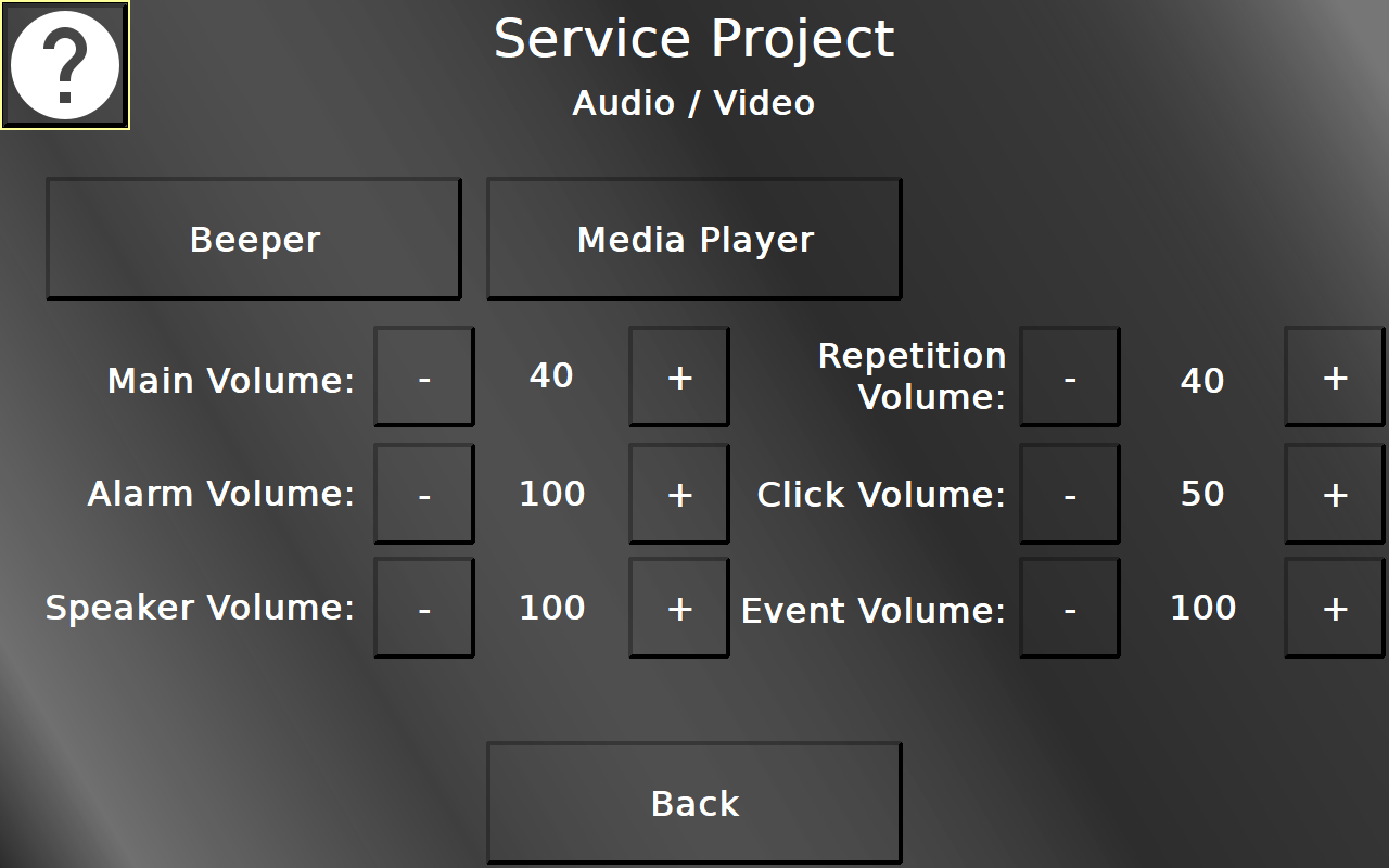
In this screen most volumes for speaker / beeper can be set and the Beeper and Media Player pages can be reached.
Back returns to the main menu.
Service Project -> Audio / Video -> Beeper
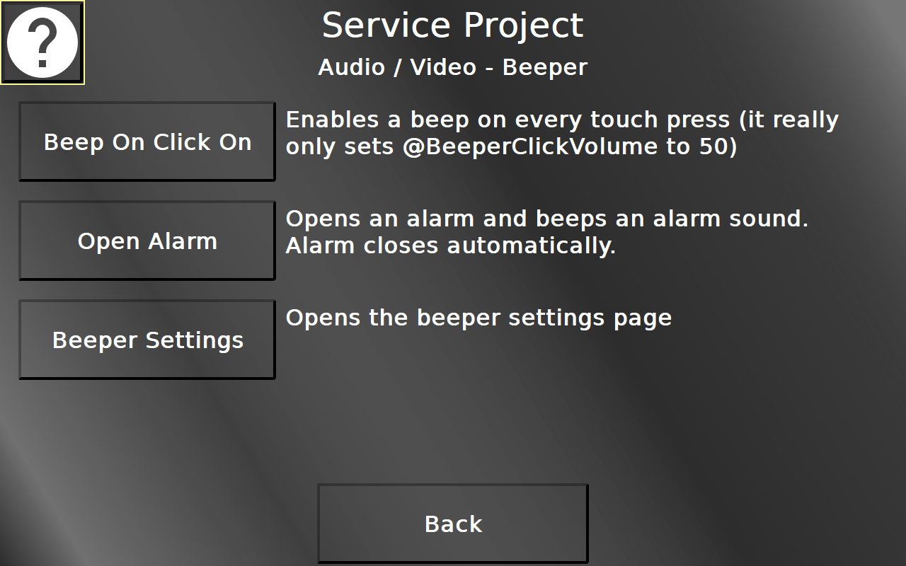
In this screen the beep on click function can be enabled / disabled. With this enabled, the device will beep whenever the touch screen has been pressed.
Additionally, an alarm can be opened which also triggers a beep. The alarm will close itself after 2 seconds.
Finally, the Beeper Settings Page can be reached.
Back returns to the Audio / Video menu.
Service Project -> Audio / Video -> Beeper Settings
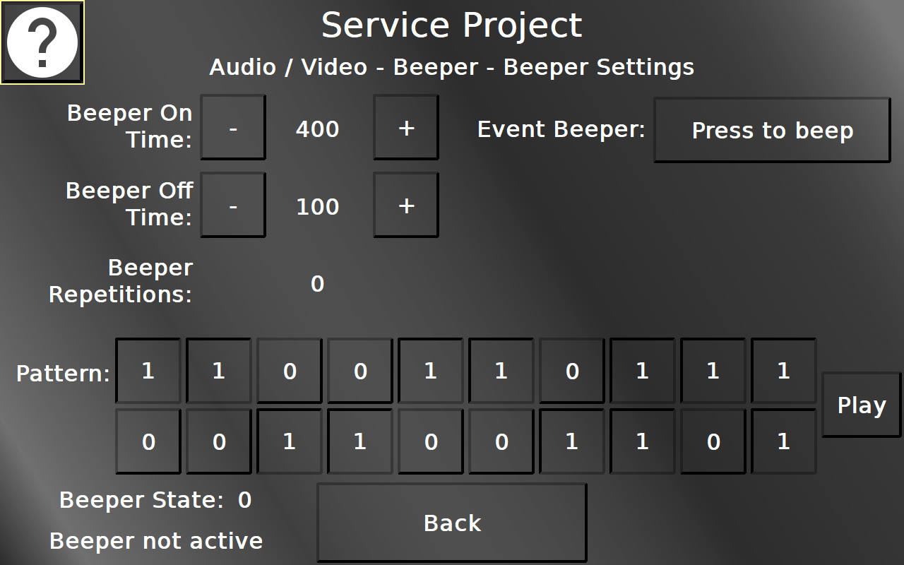
In this screen different possibilities to use the beeper / beeper simulation can be tested.
Back returns to the Beeper menu.
Service Project -> Audio / Video -> Multimedia Player
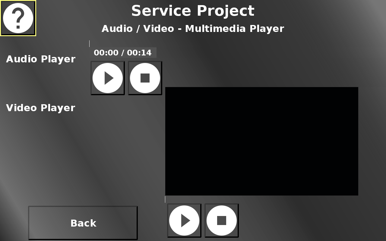
In this screen an exemplary audio and video file can be played.
Both players have a play / pause button and a stop button to control the playback.
Back returns to the Audio / Video menu.
ISO UT
With the introduction of the UT Plugin we have integrated some pages similar to the ISOBUS sample project so users can test the ISO UT functionality out of the box.
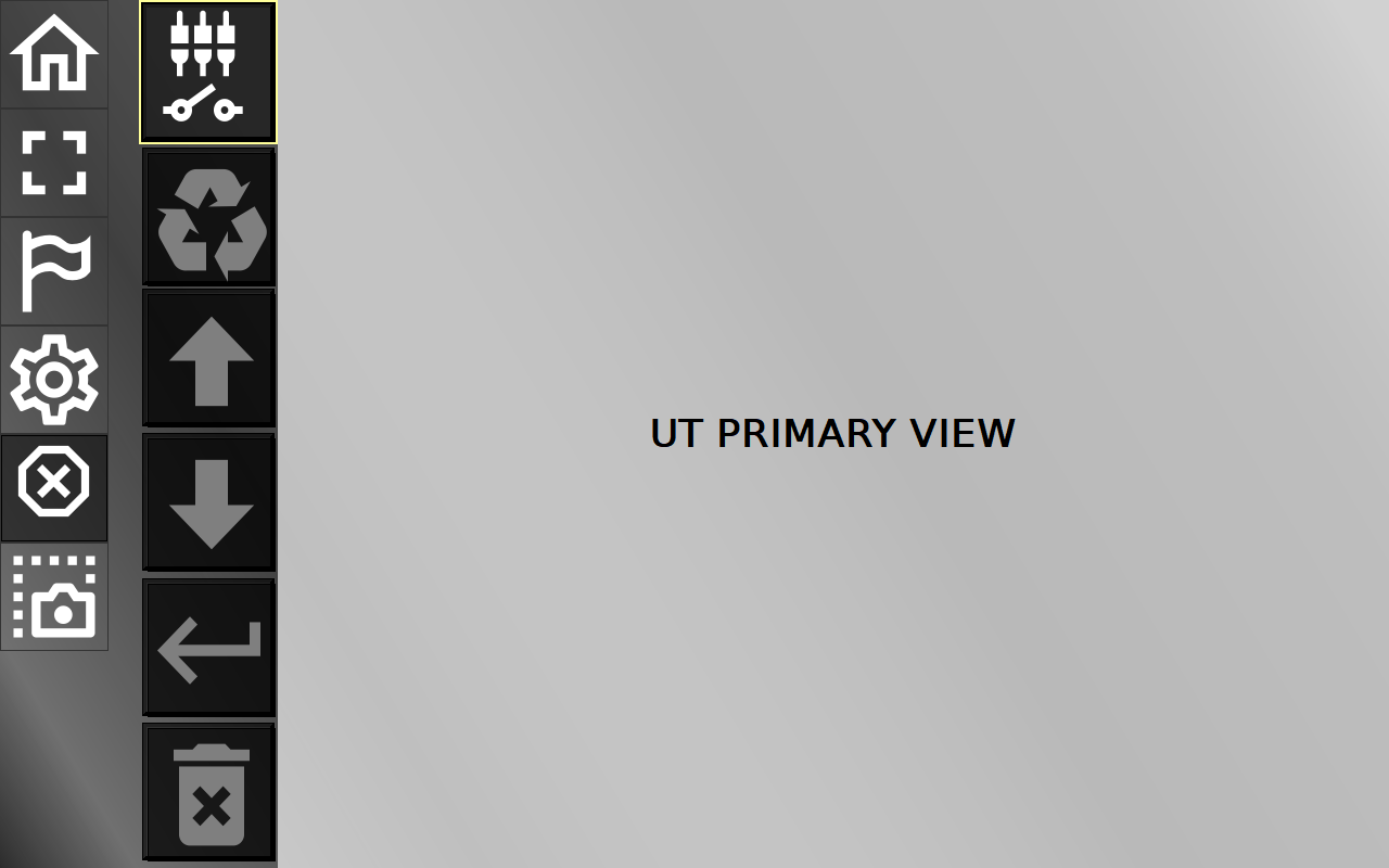
ISO UT -> Homepage
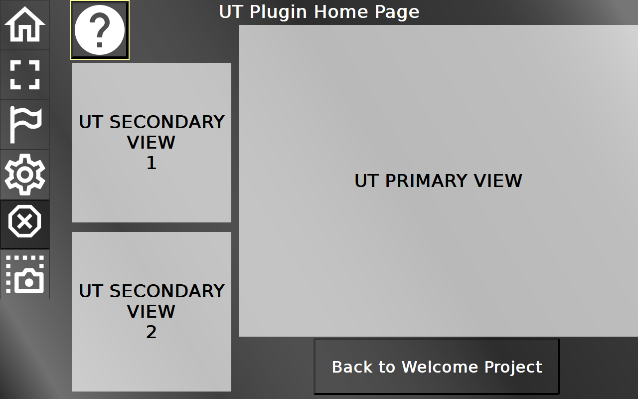
This screen shows a UT primary view and two UT secondary views. If an ISOBUS UT pool is loaded successfully, it will be shown in the primary view. If there is more than one pool, they will be shown in the secondary views. A swipe from a secondary view to the primary view will put the pool from the secondary view to the primary view and vice versa.
On the left side there are 6 soft keys to access the different pages of the ISO UT part of the Welcome Project and some functionalities, from top to bottom:
- Home button - this page
- Full Screen button - a larger primary view with some additional functions in buttons
- Language button - a configuration screen for language and unit settings
- Settings button - a configuration screen for ISO UT related general settings
- ISB button - ISOBUS ISB stop button
- Screenshot button - Creates a screenshot of the current view
These soft keys stay identical in all ISO UT pages.
The "Back to Welcome Project" button leads back to the home page of the Welcome Project.
ISO UT -> Full Screen View
In this screen the primary UT view will be shown larger. Additionally, some buttons with ISO UT related functions are displayed, from top to bottom:
- AUX configuration button - opens the AUX configuration screen
- Cycle button - cycles between loaded ISO UT pools
- Focus up button - navigates up or increases the value in the ISO UT screen
- Focus down button - navigates down or decreases the value in the ISO UT screen
- Enter button - confirms something in the ISO UT screen
- Delete pools button - deletes all cached pools (NOT currently active pools that are already loaded)
If the full screen button is pressed in this screen again, a complete full screen UT will be shown without any other objects. Only for devices without hard keys, a back button will be displayed to be able to return to the normal full screen page. If this Back button is in the way of UT content, long press it and it will jump to a different location. On devices with hard keys, press the ESC key to return to the normal full screen page.
To return to the Welcome Project home page, click the home button and then "Back to Welcome Project".
ISO UT -> Language / Unit Settings
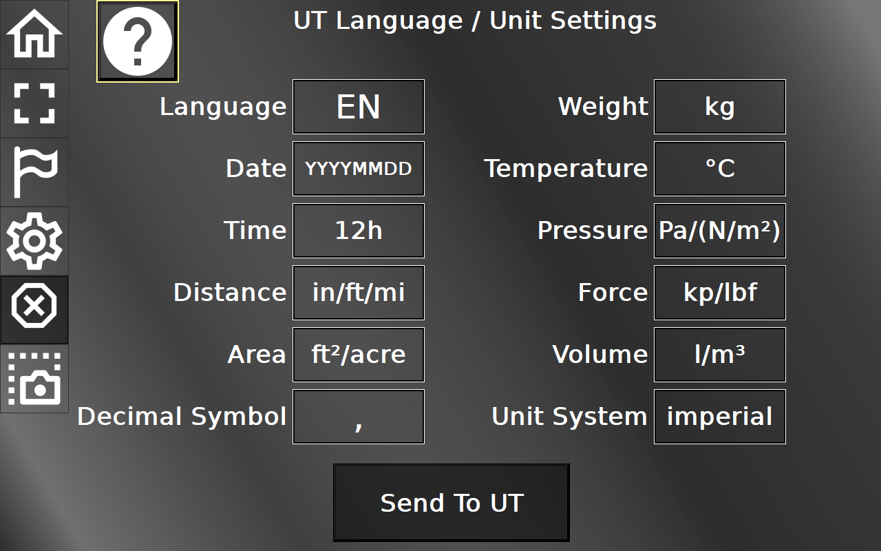
In this screen several language and unit settings can be made. The Send To UT button will send the updated settings to connected UT clients.
To return to the Welcome Project home page, click the home button and then "Back to Welcome Project".
ISO UT -> UT Settings
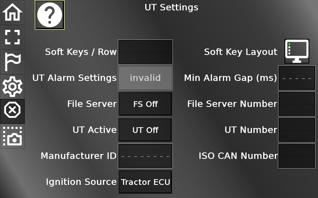
In this screen several settings regarding ISO UT can be made.
To return to the Welcome Project home page, click the home button and then "Back to Welcome Project".