This page is a follow-up of the general introduction into J1939, the general setup required to use J1939 and the creation of J1939 ECUs and their variables.
Here we create J1939 PGN mappings to communicate with ECUs over CAN bus.
![]() Tutorial video about setting up J1939 transmit mappings
Tutorial video about setting up J1939 transmit mappings
![]() Tutorial video about setting up J1939 receive mappings
Tutorial video about setting up J1939 receive mappings
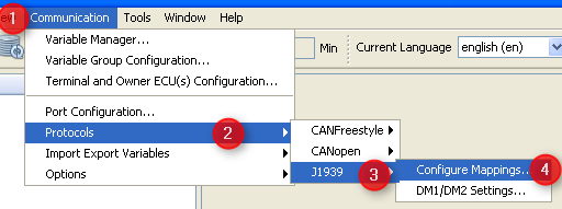
After having defined an ECU as variable owner and the variable itself we finally have to define the connection between these two. In other words: We need a definition about how to exchange the variable's value with the ECU. These definitions are called "variable mappings" within this tool and for J1939 protocol the variable mapping defines the PGN. In order to define a PGN or J1939 variable mapping you can either use the shortcut button of the variable manager shown in the image above or open the respective dialog from the menu as follows or, alternatively, click the J1939 mapping shortcut inthe toolbar:
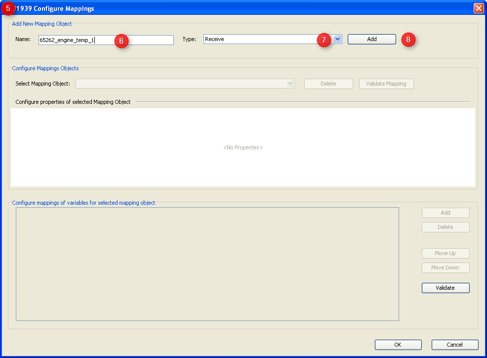
1.Open menu "communication". 2.Select "Protocols". 3.Choose "J1939" 4.Select "Configure Mappings ...". 5.The "J1939 Configure Mappings" dialog will pop up. 6.Type the name of your PGN mapping - in the example we want to define PGN 65262 "Engine Temperature 1" defined in J1939-71 7.Select type "Receive" if the display should fetch values from CAN bus and "Transmit" if the display should send out values. 8.Press "Add" to create the new mapping. |
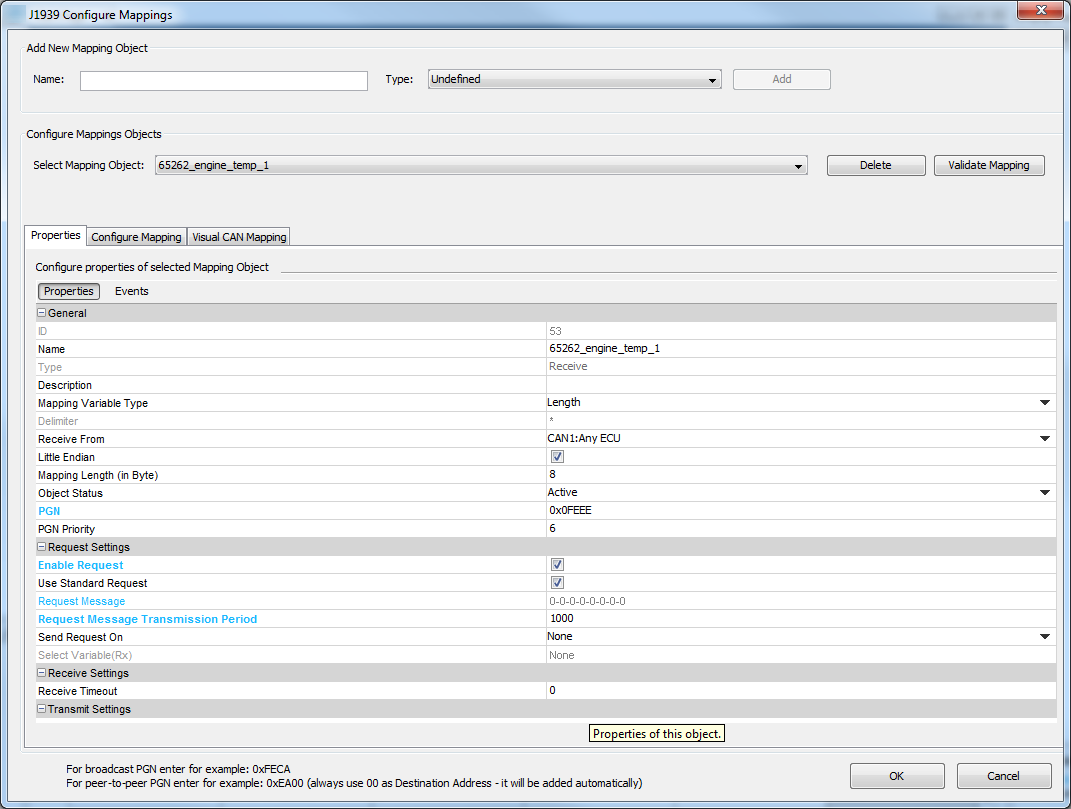
The dialog will populate with the default setting for the new mapping object which have to be modified according to your intentions:
|
IDIs the object ID internally created which can not be modified. NameThe name of the mapping as used during creation. This name can be edited here. Type"Receive" or "Transmit" - this property can not be modified. If this needs to be changed you have to delete and recreate the mapping. DescriptionShould be a valid description of the mapping which helps understanding its purpose and context in future. MappingVariable TypeThere are two types of mappings in this context: •Length based mappings find every variable (or constant) by position and length within the CAN message. If length based mappings are less than 8 bytes long their variables or constants can be placed at any position. If they should be longer the variables and constants have to be byte aligned. •Delimiter based mappings look for a dedicated separator character placed between the variables and find the variable based on count of these delimiters. Delimiter based mappings are typically bigger than one CAN message and have to be byte aligned. If a string variable is mapped the value is fully written to the variable even if it should be longer than the length defined for the variable. DelimiterOnly gets enabled if "Delimiter" is chosen in "Mapping Variable Type" above. Then you can set the separator char to be found in the message. Receive from / Transmit toFor receive mappings/PGNs: Select the ECU who has to send the PGN where the variable should be extracted. "Any ECU" is a wildcard meaning "don't care for the source address and accept this PGN from anyone". For transmit mappings this property describes the destination address to be used in the PGN. Please note that some PGNs are broadcasts by definition so that this property will be ignored for them. See also message format. Little EndianJ1939 values are transferred least significant byte first (little endian) by default. Since some manufacturers opt for big endian format in their proprietary J1939 messages you can configure this here for the whole mapping. If you should have a PGN which contains both types you have to create two separate mappings. This setting only applies to numeric values. Strings are expected to be "big endian" i.e. the first byte of the word or sentence is the first one on the bus. Mapping LengthEnter the data length of the message you want to configure. The length has to be between 0 and 1785 bytes. Between 0 and 8 bytes, the data length of the mapping and the incoming message are compared. Only if they match, the data will be put into the mapped variables. Object StatusWith Object Status Active the mapping is working, i.e. it is processing received messages or sending them. With Object Status Inactive the mapping is not working. This property can be switched at run time with the setProperty JavaScript function to enable / disable CAN mappings. PGNEnter the PGN number in decimal of hexadecimal format (starting with "0x"). The value will anyways be displayed in hexadecimal format. In our example PGN 65262 is displayed as 0xFEEE. PGN PriorityFor receive mappings this is ignored. For transmit mappings this priority is used when sending the message. Priority can be any value between 0 (highest) and 7 (lowest). See also message format. |
These settings define if and when the display sends a request (for receive mappings) or answers a request with a transmit mapping. In any case the display answers the "request for PGN" if it has a transmit mapping configured for the requested PGN. The only pre-requisite is that the ECU sending the request is "known" i.e. it claimed an address before or is listed as owner ECU in the GUI definition. Enable RequestFor receive mappings this means that the display will send out a request to get the PGN based on the following settings. For transmit mappings this means that the request defined in the following properties will be recognized and answered with the transmit mapping. Enabling this is only required if there is a request to be recognized that is NOT the PGN 0x00EA00 == 59904 == "request for PGN" as defined in J1939 standard. Use standard requestOnly appears for receive mappings. If enabled the display will send out a "request for PGN" based on the following triggers. Request messageIs only enabled for receive mappings where "use standard request" is not set. This allows definition of a PGN with fixed data section which will be sent out in order to get the receive mapping based on the triggers below. Depending on the "Receive from" setting this PGN will be sent to the ECU who should provide the mapping or as a broadcast. One can select all three proprietary types of PGNs for this request. Note: PGNs 0xff00 ... 0xffff are broadcast by definition. See also message format. Request Message Transmission PeriodIs only enabled for receive mappings. This defines the interval in milliseconds the display will send requests for the mapping. Set to 0 if no periodic request is required. Send Request On•"Specific Variable Change" allows triggering the request based on any variable in GUI definition. •"None" means there is no trigger besides the time based one. Select Variable (Rx)Only enabled if this is a receive mapping, request is enabled and "Send Request On" is set to "Specific Variable Change". This allows setting the variable whose value change should trigger sending the request. |
Receive TimeoutThis is intended for receive mappings which are expected to arrive periodically - either by default or by periodic request. If the mapping is not received in as many milliseconds as defined here all variable values of the mapping are considered invalid and hence all DDOs showing them will also be disabled. |
Use as Write RequestIf checked this means that the transmit mapping will be sent out once if there is a write request to one of the variables contained in the mapping. Usually the display only sends values provided by the owners of the respective variables in transmit mappings. This means that e.g. engine speed will only be sent out as provided by engine ECU. If in your system modifying the measured engine speed value is used to set a new desired engine speed then you can check this property and writing on the engine speed variable will send out the transmit mapping containing the new setpoint of the engine speed value. Please note that all other values in the mapping will be the ones provided by their respective owners and even the new setpoint will in the next message be replaced by the last measured value provided by the owner. If you should want to write to the same variable from many sites you should consider "PClient" as the variable owner which will accept all write requests but whose variables will never become invalid again once they have a value. Send Value On•None: Mapping is only sent time based (if configured) and on request. •Any Variable Change: Whenever one of the mapped variables changes its value the mapping is sent out. •Specific Variable Change: The mapping is sent out if the variable specified in the following property changes its value. Select Variable (Tx)Choose the variable whose value change should trigger sending out the mapping. This variable can be part of the mapping but doesn't have to be. Transmission Period (in ms)Defines the interval between messages for this transmit mapping. Set to 0 if time based sending is not desired. |
This tab allows adding actions to mapping related events. It only appears for receive mappings. The configured actions for the events are executed directly in the CAN thread when the event happens. The CAN stacks will wait until the actions are executed.
OnReceiveTimeOutActionThis event is triggered if a receive mapping is not received within the period defined as "Transmission Period". If this happens all the variables mapped to the PGN are automatically considered invalid and additionally the action is executed. If you should see any "Event Options" for this event - ignore them like the PClient does. Possible actions that can be assigned are •"No Action" which is the default •"Set Value" to assign a constant value to a variable, e.g. to reset a counter, raise an alarm or trigger something attached to a variable where "Force Writing" is true. •"Execute Script" allows to execute a script and provides additional parameter "Execute on every Xth Event" so that it is possible to execute the script only for e.g. every third timeout. OnReceiveTimeOutResolvedActionThis event is triggered if a receive mapping which time out before is received again. If this happens all the variables mapped to the PGN are automatically considered valid again (assuming the PGN received really contained a value for them) and additionally the action is executed. If you should see any "Event Options" for this event - ignore them like the PClient does. Possible actions that can be assigned are •"No Action" which is the default •"Set Value" to assign a constant value to a variable, e.g. to reset a counter, raise an alarm or trigger something attached to a variable where "Force Writing" is true. •"Execute Script" allows to execute a script and provides additional parameter "Execute on every Xth Event" so that it is possible to execute the script only for e.g. every third timeout.
OnMappingReceivedThe action for this event is executed EVERY TIME the mapping is received (regardles of value changes). When a script action is executed, the variables used in the mapping will already have been updated with the values from the CAN message. Do NOT execute complex scripts at this event if the mapping is received very often! Monitor the performance on the device with a realistic cycle time of all CAN messages. Monitor the cycle time of transmit messages (the CAN stack has to wait until the received action is over before taking care of other tasks like sending out transmit mappings). If you should see any "Event Options" for this event - ignore them like the PClient does. Possible actions that can be assigned are •"No Action" which is the default •"Set Value" to assign a constant value to a variable, e.g. to reset a counter, raise an alarm or trigger something attached to a variable where "Force Writing" is true. •"Execute Script" allows to execute a script and provides additional parameter "Execute on every Xth Event" so that it is possible to execute the script only for e.g. every third timeout. |
After setting all the general properties of the mapping now the data part has to be defined. Some general rules apply: •All variable and constant positions define the position of the least significant bit (for little and big endian) •Receive mappings can have gaps - as long as the length can be determined. •Receive mappings are recognized if all the following conditions are true: if ( ( (PGN received) == (PGN configured) ) && ( (ECU source address) == (ECU configured) ) && ( (message length) == (message length configured) ) && ( ((constants received >> shift) AND configured mask) == ((constants configured >> shift) AND configured mask) ) ) Note: It is allowed to leave gaps in the data section of receive mappings. Note: The last condition allows covering multiplexed PGNs by defining a separate mapping for each value of the multiplexer Note: Message length is only compared if less than 8 bytes are defined. For messages with flexible size or other reason to ignore length, make sure configure the length of the message to a value >8.
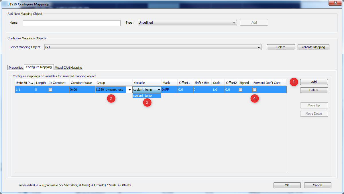
Assume we want to complete the definition of our "Engine Temperatures 1" PGN so that we can get the coolant temperature from it. We only have to add the definition of the "engine coolant temperature" value. The length of the message is defined in the message length property.
1.Press "Add" button to add a line to the mapping. 2.Select the group of the variable to map. 3.Select the variable itself. After doing this the properties in the line adjust to the variable definitions made earlier e.g. the length is set to 8 bits and the mask is set to 0xff meaning all the bits will be taken. The variable mapping can also be done in the Visual CAN Mapping. Please note, for J1939, if in a variable all bits are set to 1, this is defined as "don't care" in most cases. Therefore, if a received messages contains all 1s for a variable, this variable will not be written with that value. If the variable should still be set with that value of all 1s, activate the option "Forward Don't Care" (4). |
The following settings can be made for each variable added to the mapping: Byte Bit PositionPosition is shown as byte#:bit# where byte 1 is the byte closest to the CAN identifier and bit 1 is the least significant bit of a byte. I.e. full CAN message starts with byte 1 directly behind the CAN ID and ends with byte 8. In a byte with value 1 bit 1 is set, in a byte with value 128 bit 8 is set. These enumeration scheme matches the one used in J1939 standard documents so that you can directly copy the position. Engine coolant temperature is defined as the first byte - so set start position to 1:1. Alternatively one can type the bit position directly: 1 refers to the bit closest to the CAN identifier and 64 is the bit at the end of the CAN message. Warning: This input does not always behave as expected when typing position by hand. Finally the displayed "byte:bit" value is relevant. The mapping is filled correctly if there are no gaps i.e. the whole message gets filled with values. Please refer to the following image for byte and bit enumeration within a CAN message. This enumeration is valid for little and big endian variables since it only refers to the CAN message itself.
LengthDefines the size of the mapped numeric variable or constant in bits. If a string is mapped this defines the length of the string in bytes. Mapped length can be shorter than the length defined for the variable but not longer. By default the variable length is used. Is ConstantEnable this checkbox to define a constant. Depending on the mask constants can be used to fill gaps or recognize multiplexers in receive mappings. In transmit mappings constants are required for every part of the message not filled with a variable. Uncheck this property to map a variable. Constant ValueAlthough appearance does not change this property is only valid and editable for constants i.e. lines where "Is Constant" property is set. If valid this defines the numeric value of the constant. Please note that constants are always expected to be numeric - there is no option to define string constants. GroupVariable group containing the variable to be mapped. Does not apply to constants. VariableThe variable to be mapped. MaskVariable or constant are bitwise ANDed with mask before they are applied. See receive condition on how this can be used to receive multiplexed PGNs. See section mapping calculations for details about how this property applies to receive and transmit mappings. Offset1Offset 1 is a decimal value applied to the received value after mask and shift factor but before scale and offset 2. See section mapping calculations for details about how this property applies to receive and transmit mappings. Values can be entered in decimal form or in scientific notation / floating-point representation. Shift X BitsShift received value to the right by as many bits as defined here. Negative values shift to the left. This value is applied after the mask but before offset and scale. See section mapping calculations for details about how this property applies to receive and transmit mappings. ScaleDecimal value to scale the received value before applying it to the mapped variable. Is applied after mask, shift and offset 1 but before offset 2. Values can be entered in decimal form or in scientific notation / floating-point representation. Offset2Decimal value applied after all the other calculations are done. See section mapping calculations for details about how this property applies to receive and transmit mappings. Values can be entered in decimal form or in scientific notation / floating-point representation. Mapping calculationsThe calculations applied to a mapping are defined mainly for receive mappings - in case of J1939 they can be directly derived from the resolution and offset defined in the standard. For transmit mappings all calculations are inverted so that the same values can be applied to receive and transmit mappings. The formula converting a mapped area of a CAN message into the variable value is as follows:
variable_value = (((( CAN_value >> shift ) & mask ) + offset1 ) * scale ) + offset2
Consequently the calculation applied to transmit mappings inverts the above:
CAN_value = (((( variable_value - offset2 ) / scale ) - offset1 ) & mask ) << shift
Note: For constants only "shift" and "mask" are applied. Note: Currently signed/unsigned calculation is performed based on variable definition. If variable is signed this means the CAN_value is considered negative if the most significant bit of the mapped area is set. This leads into some issues with J1939 values which are transmitted unsigned but should be displayed in signed format (as described in example below). |
Coming back to the example of "Engine Temperatures 1" PGN we would set the following values:
This will correctly provide temperatures from 0 ... 210 °C since we defined the variable as "unsigned". CAN values 0 ... 39 will be converted into high unsigned values by Offset1. Alternatively we could have defined the variable as "signed" so that temperatures of -40 ... 87 °C would be displayed correctly. Then higher values would be interpreted as negative and the offset of -40 would make them even more negative. It is planned to solve this by defining the CAN format independent of the variable format. Until this works one could either live with the limitations described above or as a workaround use the signed variable type and map one more bit than transmitted and then reduce it with the mask to the correct size. This would require one unused bit next to the variable though. |


