![]() Tutorial video about setting up J1939 DM1 / DM2
Tutorial video about setting up J1939 DM1 / DM2
For receiving and displaying the contents of DM1 and DM2 messages various settings can be made.
Please note that only conversion method 4 is used for the processing of DM1 messages. To cite the standard:
"Effective 1996, Version 4 shall be used for all future OBD applications"
We will focus on products newer than 1996, which is why only version 4 is supported.
To open the settings dialog use the main menu tab Communication | Protocols | J1939 | DM1 / DM2 Settings.
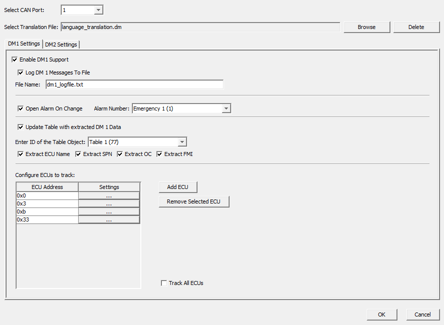
A description of all available settings follows here:
Common Settings for DM1 and DM2
Select CAN Port
Select the CAN port for which you want to configure the DM settings. Only CAN ports that have a J1939 protocol attached are available. When changing the CAN port you can choose to apply the settings you have made for the current CAN port.
Select Translation File
Using a translation file can make the viewing of the trouble codes easier. In the translation file the following translations can be made:
•ECU Address to ECU Name
•SPN to SPN Description
•FMI to FMI Description (general or SPN specific)
Example content of a translation file (for one language):
#ECU address to ECU Name translation
# syntax: ECU;ECUAddress;Translation
ECU;0x00;EMS
ECU;0x03;TECU
ECU;0x0b;EBS
ECU;0x33;TPMS
#SPN translation
# syntax: SPN;Number;Translation
SPN;110;Coolant Temp.
SPN;1119;Exh. Oxygen
SPN;161;Shaft Speed
SPN;177;Oil Temp.
SPN;521;Pedal Pos.
SPN;1091;Pressure
SPN;258856;Tire F_L
SPN;258857;Tire F_R
SPN;258866;Tire R_F_L
SPN;258876;Tire R_R_L
SPN;258867;Tire R_F_R
SPN;258877;Tire R_R_R
#General FMI codes. Used if no SPN specific FMI was declared
#Syntax: FMI;Number;Translation
FMI;0;Above Normal
FMI;1;Below Normal
FMI;2;Data Erratic
FMI;3;Voltage Above Normal
FMI;4;Voltage Below Normal
FMI;5;Current Above Normal
FMI;6;Current Below Normal
FMI;7;Mech. Sys. Not Responding
FMI;8;Abnormal Frequency
FMI;9;Abnormal Update Rate
FMI;10;Abnormal Rate of Change
FMI;11;Root Cause Unknown
FMI;12;Bad Device
FMI;13;Calibration
FMI;14;Special Instructions
FMI;15;Above Normal (Least)
FMI;16;Above Normal (Moderate)
FMI;17;Below Normal (Least)
FMI;18;Below Normal (Moderate)
FMI;19;Recv. Network Data in Error
FMI;20;Data Drifted High
FMI;21;Data Drifted Low
FMI;31;Condition Exists
#SPN specific FMI codes.
#Syntax: SPNFMI;ECUAddress;SPN;FMI;FMITranslation
SPNFMI;0x0b;521;0;Pedal position too high
The Translation File is valid for both DM1 and DM2 messages.
If the project is a multi-language project, other language translations can be added to the existing lines. Here are some examples for two languages:
#SPN translation
# syntax: SPN;Number;TranslationLanguage0;TranslationLanguage1
SPN;110;Coolant Temp.;Kuehltemperatur
SPN;177;Oil Temp.;Oel Temperatur
SPN;1091;Pressure;Druck
#General FMI codes. Used if no SPN specific FMI was declared
#Syntax: FMI;Number; TranslationLanguage0;TranslationLanguage1
FMI;0;Above Normal;Ueber Normal
FMI;1;Below Normal;Unter Normal
#SPN specific FMI codes.
#Syntax: SPNFMI;ECUAddress;SPN;FMI;FMITranslationLang0;FMITranslationLang1
SPNFMI;0x0b;521;0;Pedal position too high; Pedal Position zu hoch
Please note that the sequence of the languages corresponds to the configured language indices (see Project Properties => Languages)
Please also note that there is a maximum line length the translation file can have. This limit is 32767 characters. If one line exceeds this limit, the translation file may not be parsed correctly.
You can use a text file encoded in UTF-8 format to include special characters, chinese, kyrillic characters and so on.
DM1 Settings
Enable DM1 Support
With this checkbox the DM1 support can be enabled or completely disabled.
Log DM1 Messages To File
It is possible to log all DM1 DTCs to a file. Just enable the checkbox and enter a log file name. If you choose .csv as suffix, it is easy to open that log file in Excel or in another spreadsheet application.
Every DTC will be logged in a separate line. A date- and timestamp will be placed before each DTC. If you have selected a translation file, the DTC components will be translated.
Which DTC components will be logged, you can decide with the “ExtractXXX” settings (see below)
The log file will be stored on the device in the directory /opt/logfiles/. The variables @CurrentDirectory, @CurrentFile, @DestinationDirectory and @CopyFileOrFolder can be used to copy or move the log file to an USB stick.
Note: There is currently no restriction in the size of the log file. Please consider deleting or moving the log file to a USB stick at a regular basis (or if it becomes too big).
Open Alarm On Change
If the “Open Alarm On Change” checkbox is enabled, the Alarm Number of an existing Alarm can be entered in the text field.
Now whenever a new or changed DTC arrives in a DM message this Alarm will pop up and the currently active DTCs can be presented to the user.
Advise: place a table object inside the alarm to show all active DTCs (see below for table object settings).
Screenshot of an Alarm displaying DM1 Trouble codes in a table (with a valid translation file configured):
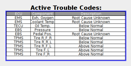
Update Table with extracted DM1 Data
When the checkbox “Update Table with extracted DM 1 Data” is enabled, the ID of an existing Table Object can be entered in the filed “Enter ID of the Table Object”.
The DTCs of a DM1 message will be extracted and passed as data to the Table Object. You can select which components of the DTC shall be passed to the Table Object by enabling or disabling the “Extract ECU Name”, “Extract SPN”, “Extract OC” and “Extract FMI” checkboxes.
If the Table Object shall only show ECU, SPN and FMI, select those three and deselect “Extract OC” (recommended for DM1 since OC is always 1 in DM1 messages). The Table Object should then be configured to have three columns.
Configure ECUs to track
In this section you can chose if you want to track the DM1 messages of all ECUs on the selected CAN port or if you want to only handle a selection of ECUs.
If you want to track all ECUs and do no filtering you can just select “Track All ECUs” in the bottom right.
If you want that not all ECU’s DM1 messages are handled, you have to disable “Track All ECUs”. After that you can click the “Add ECU” button to add a new ECU to the list of handled ECUs. Once the ECU was added, the address of the ECU can be changed by clicking in the cell in the table.
To remove an ECU from the white-list, you can just select one and hit “Remove selected ECU”.
Each ECU can then be configured if all SPNs shall be handled or only the configured ones. Furthermore it can be selected if the DM1 message of one ECU shall be passed to a specific table object. To do the settings for each ECU, click the “…” button in the “Settings” column to open the ECU settings dialog:
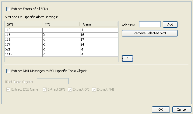
In this dialog it can be configured if all SPNs of one ECU shall be extracted or if only the configured ones shall be handled. Furthermore it can be specified if an alarm shall be triggered if a certain SPN is received in a DM1 message.
If all SPNs shall be extracted, the “Extract Errors of all SPNs” checkbox has to be enabled.
If only some SPNs shall be handled, disable the “Extract Errors of all SPNs” checkbox. Then just write the SPNs in the “Add SPN” text field and click Add or hit <Enter> on the keyboard.
The new SPN will appear in the table on the left.
If you want to remove one or more SPNs, just select it/them and click the “Remove Selected SPN” button.
After a SPN was added to the table it can be configured if a dedicated alarm shall be engaged when the SPN is included in the DM1 message. For that, the alarm number needs to be entered in the in the "Alarm" cell. The default value for that cell is -1 which means: engage no alarm.
Additionally it can be configured if the alarm shall only be engaged for a certain FMI number. Just write the FMI into the cell. The default value for the FMI cell is -1 which means: engage the alarm for any FMI.
To trigger different alarms for different FMIs, the same SPN can be added several times to the table and different FMIs and alarms can be configured.
For example take the screenshot above. It has the following SPN FMI Alarm settings:
110 |
-1 |
-1 |
|---|---|---|
116 |
0 |
16 |
116 |
1 |
17 |
177 |
-1 |
24 |
521 |
-1 |
-1 |
1119 |
-1 |
-1 |
That means:
•Track SPNs 110, 116, 177, 521 and 1119
•Don’t engage an alarm for SPN 110 (FMI and Alarm are -1)
•Engage alarm 16 for SPN 116 if FMI is 0 (FMI is 0, Alarm is 16)
•Engage alarm 17 for SPN 116 if FMI is 1 (FMI is 1, Alarm is 17)
•Engage alarm 24 for SPN 177 and don’t care for FMI (FMI is -1, Alarm is 24)
•Don’t engage alarm for SPNs 521 and 1119 (FMI and Alarm is -1)
In the lower part of the dialog, it can be selected if the DM1 message entries of the selected ECU shall be passed to a specific table object. The settings in this dialog correspond to those in the parent dialog.
By clicking the “OK” button, all settings will be saved. When clicking “Cancel” all settings will be discarded.
DM2 Settings
The only settings that can be made for DM2 messages is to enable or disable it and “Update Table with extracted DM 2 Data” setting. This setting is the same as for DM1 messages. You can enter a different Table Object ID in the “Enter ID of the Table Object” field than for the DM1 Table so that you can have different tables for both message types.
DM1 and DM2 How To
How to get DM2 messages
DM2 Messages are only sent on request. They can be either requested for single ECUs or a global request can be sent. The following example shows how to make a global request for all ECUs to send the DM2 messages.
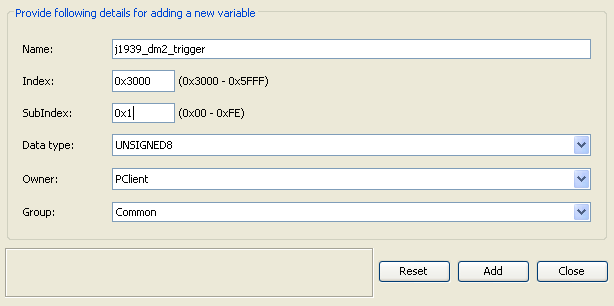
First you have to create an internal variable (Communication | Variable Manager... | button Create A New Variable) to which we can write. In this example it is called j1939_dm2_trigger, the owner is PClient and the data type is UNSIGNED8. You are free to choose index and subindex and the variable group:
Next a J1939 transmit PGN needs to be configured. Go to Communication | Protocols | J1939 | Configure Mappings.... Enter “dm2_global_request” in the “Name”, as type select Transmit field and click the “Add” button.
The PGN Id for this request is 0xea00, the priority is 6. Destination is Any ECU and for “Send Value on” select “Any Variable Change”:
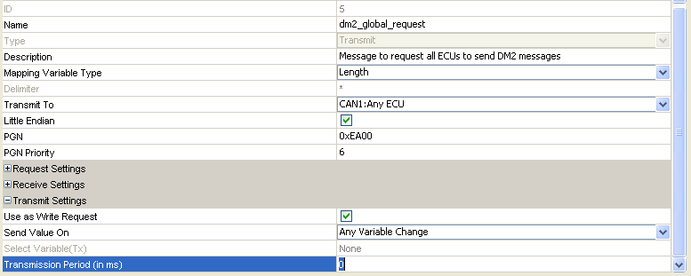
Now add two entries in the Configure mappings of variables for selected mapping object section of the dialog by pressing the Add button twice. Make the same settings as in the screenshot below:

Important is that the first 16 bit entry is constant with Mask 0xffff and the Constant Value of 0xfecb. The following byte is our j1939_dm2_trigger variable. Here the Mask has to be 0x0. Click OK on both dialogs.
How to trigger sending of this request:
Select a button or softkey in your project and attach an action e.g. to “OnRelease”. As action select “Execute Script”. Create a new script with the following content:
//Get the old variable value, increment it and set it again
//to trigger the sending of the DM2 global request.
var value = getVariableValue(“j1939_dm2_trigger”);
//overflow prevention
if (value >= 0x7fff)
{
value = 0;
}
value++;
setVariableValue(“j1939_dm2_trigger”, value);
Now every time the button/softkey is pressed and released, the DM2 request will be sent. You can also attach this action e.g. to the “Page Init” event of the page where the table is displayed.
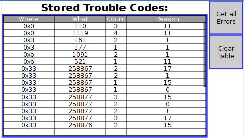
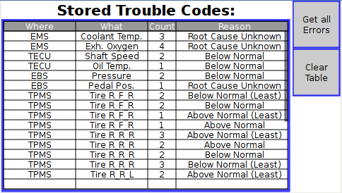
Screenshots from an example DM2 Table Object running on adevice:
First without a translation file:
And with a valid translation file:
How to clear the data of a table object
Execute a script with the following content:
var emptyArray = new Array(0);
//the first parameter of setProperty function is the Object ID,
//make sure that you enter the correct ID (probably not 291)
var tableID = 291;
setProperty(tableID, “Table Data”, emptyArray);
How to display logged DM1 messages on the device
Preconditions: Enable DM1 support. Enable “Log DM 1 Messages To File” and enter a file name. Disable “ExtractOC”.
First create a Table Object. This table should have 5 columns.
The Table Heading should be: “Date;Time;ECU;SPN;FMI”.
For updating the table with the logged DTCs, a Script has to be executed. Assign an “Execute Script” action to either a softkey’s/button’s “OnRelease” event or to the page’s “Page Init” event.
The Script has to look like this:
//Create an Array to store each line of the log file:
var logFile = new Array();
//create a string with the name of the log file (the same that was configured in DM1 Settings)
var logFileName = “j1939_DM1_log_file.csv”;
//now a variable with the default log path:
var path = “/opt/logfiles/”;
//now read the file
logFile = readFile(path + logFileName);
//after reading, the data has to be assigned to the table
//(change tableID to the tableID your table has):
var tableID = 332;
setProperty(tableID, “Table Data”, logFile);
Here is a screenshot from the device displaying the log file contents:
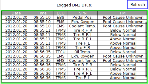
Note: You can scroll through the table if “Set As Input” property of the table is enabled.
Note 2: The JavaScript readFile function is currently limited to only read the first 2MB of a file. If the log file is larger than that, the rest of the content is not shown. Consider deleting the log file if the size of it gets too big.
DM1 Lamps
The standard SAE J1939-73 defines four lamps:
- Malfunction Indicator Lamp
- Red Stop Lamp
- Amber Warning Lamp
- Protect Lamp
The status of these lamps is transmitted in the DM1 messages of each ECU in bytes 1 and 2. Each lamp has a status value (byte 1):
bits 8-7 |
Malfunction Indicator Lamp Status |
|---|---|
bits 6-5 |
Red Stop Lamp Status |
bits 4-3 |
Amber Warning Lamp Status |
bits 2-1 |
Protect Lamp Status |
and a flashing indicator (byte 2):
bits 8-7 |
Flash Malfunction Indicator |
|---|---|
bits 6-5 |
Flash Red Stop Lamp |
bits 4-3 |
Flash Amber Warning Lamp |
bits 2-1 |
Flash Protect Lamp |
There are 8 predefined internal variables available that represent these values (read-only). The variables are available in the group J1939 and are named
•@MalfunctionIndicatorLampStatus
•@RedStopLampStatus
•@AmberWarningLampStatus
•@ProtectLampStatus
•@MalfunctionIndicatorLampFlashing
•@RedStopLampFlashing
•@AmberWarningLampFlashing
•@ProtectLampFlashing
The @XXXLampStatus contains the combined information of the status and flashing bits in the DM1 message with 16 possible combinations. The @XXXLampFlashing variable contains the direct "is it on or not?" information, when the lamp is flashing, it will change value between 0 and 1, if the lamp should glow, it will stay 1. So normally only the @XXXLampFlashing variable is needed to display the lamps by creating a list object with two images (an on and an off lamp image) and connecting it with the @XXXLampFlashing variable.
The following table shows the possible values of the DM1 message bytes and our variables. The calculation is the same for all the four variables:
Value for Status read from DM1 messages (Byte 1) |
Value for Flashing read from DM1 messages (Byte 2) |
value of @XXXLampStatus |
value of @XXXLampFlashing |
|---|---|---|---|
0 |
0 |
0 |
0: Lamp Off |
0 |
1 |
1 |
0: Lamp Off |
0 |
2 |
2 |
0: Lamp Off |
0 |
3 |
3 |
0: Lamp Off |
1 |
0 |
4 |
0/1: Flashing 1Hz |
1 |
1 |
5 |
0/1: Flashing 2Hz |
1 |
2 |
6 |
0: Lamp Off |
1 |
3 |
7 |
1: Lamp On |
2 |
0 |
8 |
0: Lamp Off |
2 |
1 |
9 |
0: Lamp Off |
2 |
2 |
10 |
0: Lamp Off |
2 |
3 |
11 |
0: Lamp Off |
3 |
0 |
12 |
0: Lamp Off |
3 |
1 |
13 |
0: Lamp Off |
3 |
2 |
14 |
0: Lamp Off |
3 |
3 |
15 |
0: Lamp Off |
As can be seen in the table above the status 2 and 3 for the lamp status and value 2 for flashing will always switch off the flashing variable. If the used ECUs support these states, a custom handling of these values needs to be developed manually by using the value of the @XXXLampStatus variables.
If multiple ECUs send DM1 messages, the lamp stati and flashing information will be combined from all messages. The priority (highest to lowest) is: Fast Flashing, Slow Flashing, On, Off.
To enable the calculations for the lamp variables DM1 support needs to be enabled.