CANFreestyle is a simple proprietary protocol, without e.g. the complexity of a transport protocol. So this protocol is very easy to use. Anyway you can modify CAN values that you want to send on the bus as well as the CAN values that you received from the CAN bus. The modifiers are the same as for J1939. Actually CANFreestyle provides a way to emulate other CAN protocols that are not supported natively. To prevent confusion, CANFreestyle will be treated as a protocol in the manual. Additionally you can create a sequence of several CAN messages which can be sent periodically. |
Before you can use the CANFreestyle protocol, it has to be activated. Before activating it the Port Configuration has to be set.
|
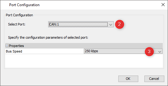
Once the port is configured the protocol itself has to be assigned to it.
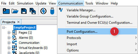
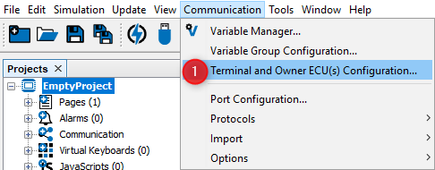
1.Open "Communication" menu and choose "Terminal and Owner ECU(s) Configuration ...". The "Terminal and Owner ECU(s) Configuration" dialog will appear 2.Press on the arrow and select CANFreestyle protocol for the CAN port you want it to run on 3.Press "Add" to use this protocol with your GUI on the display
|
1.Select CANFreestyle on the CAN port configured before - in our example we configured it for CAN 1. 2.Type a valid name and description - these are mainly for your convenience and may help others to understand the GUI configuration in future. |

 Properties of Owner ECU(s)
ECUs are configured in the same "Terminal and Owner ECU(s) Configuration" dialog that was used above to activate CANFreestyle protocol and to configure the display's address. ECUs are configured in the lower part of this dialog:
1.Type a name describing the ECU 2.Press "Add"
Then the new ECU will automatically be selected and one can modify the other parameters:
3.Provide a description that could help others to understand better which ECU is meant here 4.In case the ECU is not needed anymore it can be deleted again. If it already owns any variables, the owner will be changed to the display (PClient) when you delete it. |


As mentioned above we mainly configured the CANFreestyle ECUs because they own some variables whose values we want to show and/or modify on the display. Before we can use these variables we have to do two things: 1.Create the variables and use one of the CANFreestyle ECUs as owner. 2.Define the Mappings we want to use to send and receive the variables.
|
Knowing that we could end up with a lot of variables per ECU it's a good idea to create one variable group per ECU. Of course you are free to organize variables in groups however you prefer.
1.Open Menu "Communication" 2.Select "Variable Group Configuration ..." 3.In the dialog that opens press "Add Group" to create a new variable group 4.Type a sensible name for the new group
5.Once you pressed "Enter" to confirm the new group name it will move according to alphabetical order of all groups. 6.Press "close" once you're finished creating or deleting variable groups. |


Creation of CANFreestyle variables is similar to all other variables
1.Open the "Communication" menu and choose "Variable Manager ..." entry 2.Variable Manager dialog opens (which can be used as shortcut to all variable related tasks) 3.Press "Create a new Variable ..." button 4."Add new variable" dialog opens 5.Fill in a name of the variable 6.Type an index for the variable. You are free to enter the value in decimal or hexadecimal, starting with "0x". Anyways hexadecimal will be displayed. (Although the concept comes from CANopen you should use index and subindex as a means of ordering and grouping of variables) 7.Add a subindex for the new variable. Note: Combination of index and subindex has to be unique among all variables in the GUI definition. 8.Select signed or unsigned data type at least as wide as the variable will be in CAN message. 9.Change owner from default "PClient" to the newly created CANFreestyle ECU. Note: If you keep "PClient" you could handle the variable also but would not notice if the ECU is not available anymore. 10.Select the newly created variable group for the variable. 11.Press "Add" to finally create the new variable with the settings made above.
If the variables was created successfully the above message will be shown at the lower left box of the dialog. Now you can either create more variables by editing the settings with or without "Reset" or leave the dialog with "Close".
After closing the "Add New Variable" dialog you can modify all the properties of the variable(s) just created or already existing in "Variable Manager" dialog:
For a detailed description of all the variable properties and events please refer to variable view.
There is a second option to create variables:
1.In variable view press the "Var +" button 2.A new variable with default settings appears 3.You can double click each property and edit it.
Warning: If you type a group name that was not defined yet, a new variable group will be created. Warning: Depending on your sorting option the variable can "disappear" whenever a modification is confirmed. More details on this option can be found in variable view. So the recommendation is to create variables following the first option and use variable view to manage and modify existing variables. |


If you only want to evaluate specific bits of the CAN Identifier you can use "CAN ID Masks..." to create our own mask. This can be used for example if several ECUs are connected to the bus whose use same kind of identifier.
1.If you want to edit CAN ID Masks you can find it in the main menu like shown above. A new dialog CAN ID Mask will be open. 2.For performance reasons you can only define 6 CAN ID Masks 3.Two masks are predefined."Full 11 bit ID 1" and "Full 29 bit ID 2". So if you don't need to filter the CAN ID you can use the predefined ones. 4.If you want to add your own proprietary mask you have to press the "Add" button If the "Add" button is pressed a new line will be added at the table which is editable.
5.Here you can specify a name for the newly created mask. 6.You have to specify if the mask should be used for 11 or 29 bit CAN Identifiers. 7.In the field ID Masks you can specify the bits which should be evaluated for the CAN Identifier in hexadecimal format. 8.Deletes the currently selected mask. NOTE: The predefined mask can not be deleted. 9.To save the settings you have to press the "OK" button The created Masks can be used here. |


After having defined an ECU as variable owner and the variable itself we finally have to define the connection between the two. In other words: We need a definition about how to exchange the variable's value with the ECU. These definitions are called "variable mappings" within this tool. In order to define a variable mapping you can either use the shortcut button of the variable manager shown in the image above or open the respective dialog from the menu as follows:
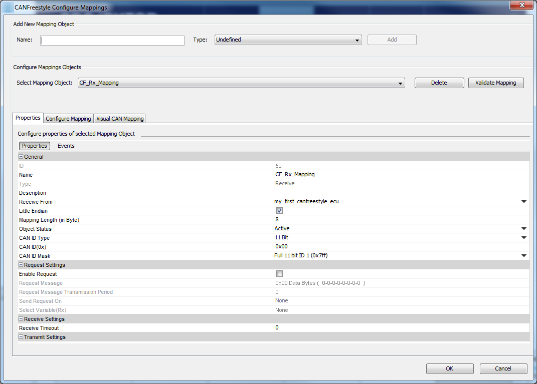
1.Open the menu "communication". Select "Protocols". Choose "CANFreestyle". Select "Configure Mappings ...". 2.The "CANFreestyle Configure Mappings" dialog will pop up. 3.Type the name of your mapping 4.Select the type "Receive" if the display shall fetch values from CAN bus and "Transmit" if the display shall send out values. 5.Press "Add" to create the new mapping. Setting Mapping PropertiesThe dialog will populate with the default settings for the new mapping object which have to be modified according to your intentions:
Defining Variable Mappings
|


The following settings can be made for each variable added to the mapping: Byte Bit PositionPosition is shown as byte#:bit# where byte 1 is the byte closest to the CAN identifier and bit 1 is the least significant bit of a byte. I.e. full CAN message starts with byte 1 directly behind the CAN ID and ends with byte 8. In a byte with value 1 bit 1 is set, in a byte with value 128 bit 8 is set. These enumeration scheme matches the one used in J1939 standard documents so that you can directly copy the position. Engine coolant temperature is defined as the first byte - so set start position to 1:1. Alternatively one can type the bit position directly: 1 refers to the bit closest to the CAN identifier and 64 is the bit at the end of the CAN message. Warning: This input does not always behave as expected when typing position by hand. Finally the displayed "byte:bit" value is relevant. The mapping is filled correctly if there are no gaps i.e. the whole message gets filled with values. Please refer to the following image for byte and bit enumeration within a CAN message. This enumeration is valid for little and big endian variables since it only refers to the CAN message itself.
LengthDefines the size of the mapped numeric variable or constant in bits. If a string is mapped this defines the length of the string in bytes. Mapped length can be shorter than the length defined for the variable but not longer. By default the variable length is used. Is ConstantEnable this checkbox to define a constant. Depending on the mask constants can be used to fill gaps or recognize multiplexers in receive mappings. In transmit mappings constants are required for every part of the message not filled with a variable. Uncheck this property to map a variable. Constant ValueAlthough appearance does not change this property is only valid and editable for constants i.e. lines where "Is Constant" property is set. If valid this defines the numeric value of the constant. Please note that constants are always expected to be numeric - there is no option to define string constants. GroupVariable group containing the variable to be mapped. Does not apply to constants. VariableThe variable to be mapped. MaskVariable or constant are bitwise ANDed with mask before they are applied. See receive condition on how this can be used to receive multiplexed mappings. See section mapping calculations for details about how this property applies to receive and transmit mappings. Mask is not used for String variables. Offset1Offset1 is a floating point value applied to the received value after mask and shift factor but before scale and offset 2. See section mapping calculations for details about how this property applies to receive and transmit mappings. Offset 1 is not used for String variables. Values can be entered in decimal form or in scientific notation / floating-point representation. Shift X BitsShift received value to the right by as many bits as defined here. Negative values shift to the left. This value is applied after the mask but before offset and scale. See section mapping calculations for details about how this property applies to receive and transmit mappings. Shift is not used for String variables. ScaleFloating point value to scale the received value before applying it to the mapped variable. Is applied after mask, shift and offset 1 but before offset 2. Scale is not used for String variables. Values can be entered in decimal form or in scientific notation / floating-point representation. Offset2Floating point value applied after all the other calculations are done. See section mapping calculations for details about how this property applies to receive and transmit mappings. Offset2 is not used for String variables. Values can be entered in decimal form or in scientific notation / floating-point representation. Empty FieldThis a simple information field. It shows a "Warning" icon if e.g a variable is not completely mapped. In the example(4) a 16 bit variable is mapped only with 8 bits, so the warning is shown. |
The calculations applied to a mapping are defined mainly for receive mappings For transmit mappings all calculations are inverted so that the same values can be applied to receive and transmit mappings. The formula converting a mapped area of a CAN message into the variable value is as follows: variable_value = (((( CAN_value >> shift ) & mask ) + offset1 ) * scale ) + offset2 Consequently the calculation applied to transmit mappings inverts the above: CAN_value = (((( variable_value - offset2 ) / scale ) - offset1 ) & mask ) << shift Note: For constants only "shift" and "mask" are applied. Note: Currently signed/unsigned calculation is performed based on variable definition. If variable is signed this means the CAN_value is considered negative if the most significant bit of the mapped area is set. |
Sequences can be used to send several transmit mappings periodically. For example it can be used as a simple kind of transport protocol. Create SequencesBefore you can create Sequences you have to define transmit mappings. For more information please have a look at chapter Defining Variable Mappings If transmit mappings are already defined please select in the main menu "Transmit Sequences..." as shown below:
1.Open Menu "Transmit Sequence..." 2.Enter a Sequence Name in the new dialog named CANFreestyle Transmit Sequence which appears. 3.Press "Add" button Afterwards following should be visible
4.Combo box where you can select the sequence you want to edit. 5.Deletes the current selected sequence. 6.Name of the transmit sequence which is currently selected 7.Here you can add a description for the sequence 8.Target owner which should receive the sequence. 9.The "Sequence ID" is a unique internal ID, which is not editable. 10.The "Period" (in ms) defines the cycle for sending the sequence. NOTE: This is the only way to trigger the sequence.
11.Select the mapping you want to add to the sequence. 12.Press "Add >>" to add the message to the sequence After adding of mapping objects the dialog should look like this:
13.If a mapping was mapped by mistake you can select the mapping and remove it again with the "<< Remove" button 14.The list box contains the transmit mapping which should be transmitted via the sequence 15.With the help of the buttons "Move Up" and "Move Down" you can change the order of the transmit mapping at the sequence Finally the dialog should be confirmed with "OK" to save the sequences. |


