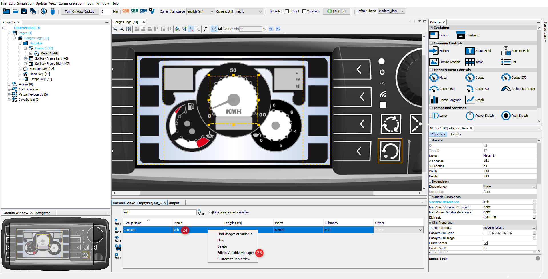
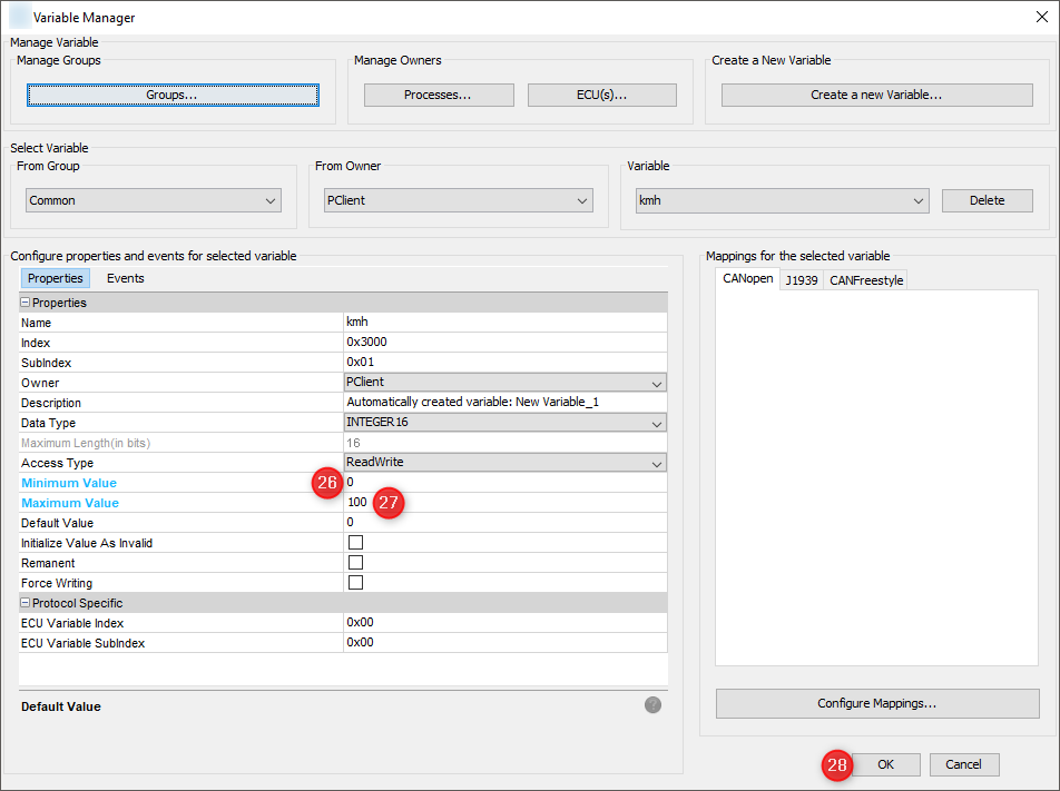
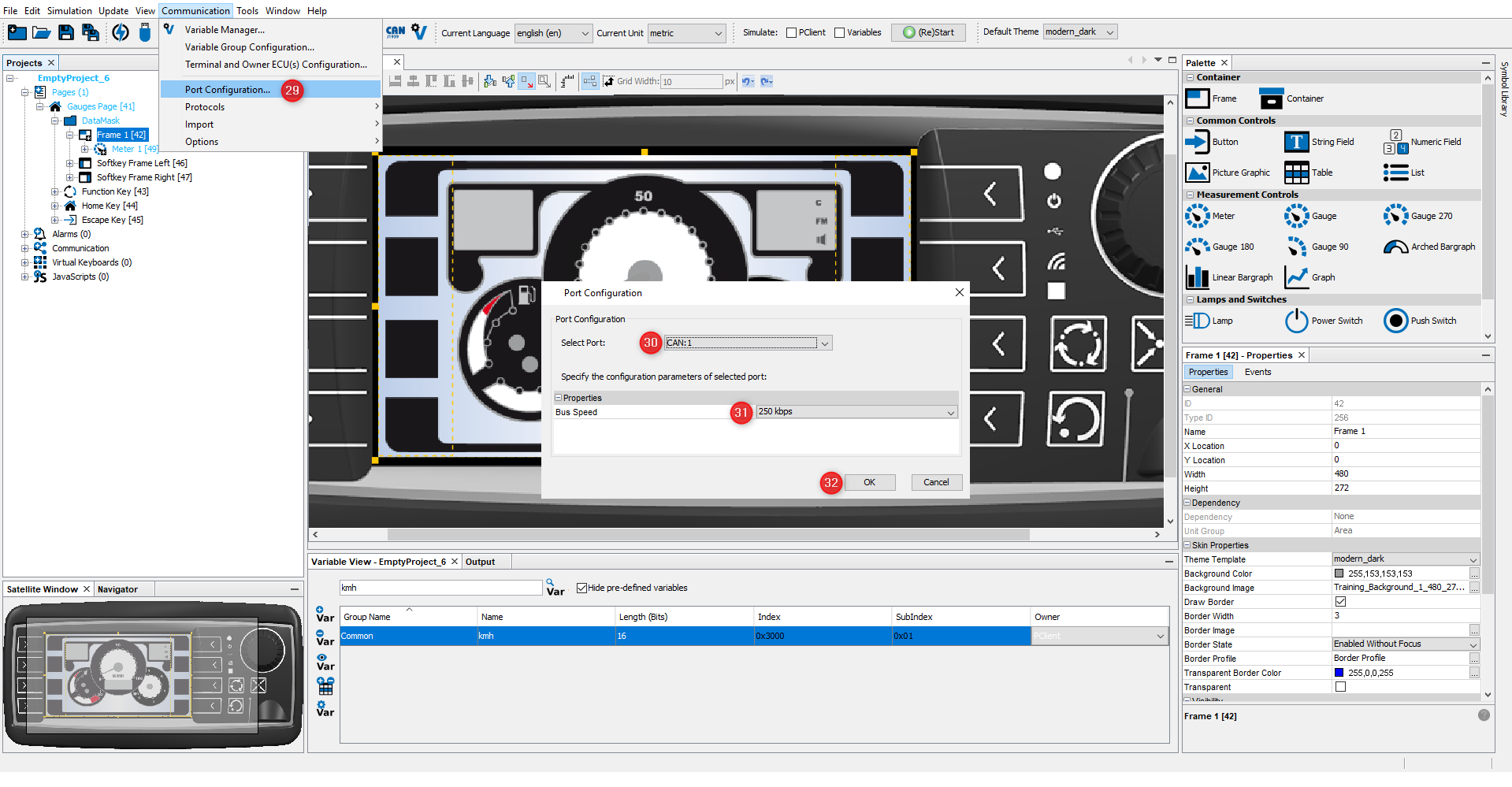
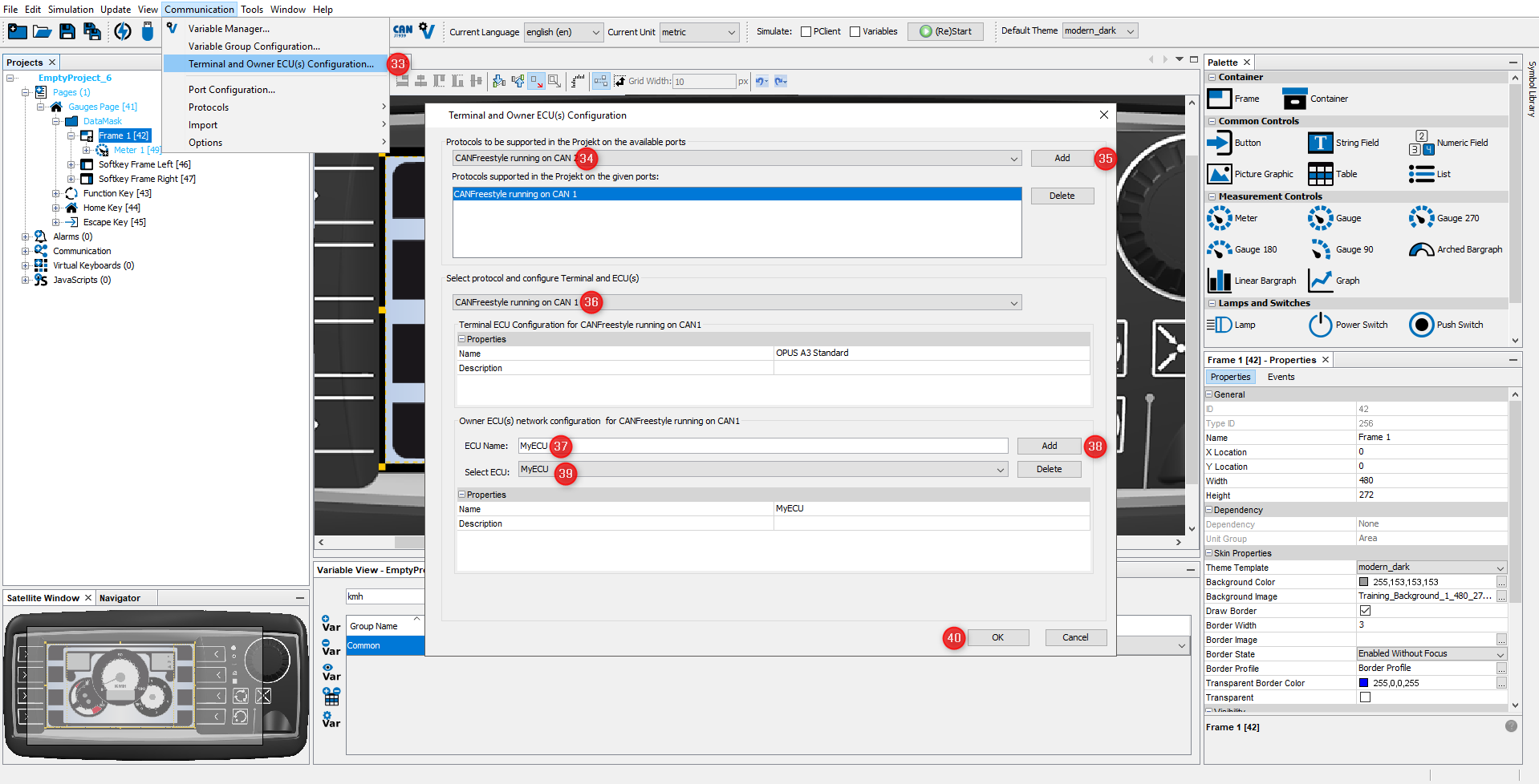
A new project always comes with a page having a default page name. By following the next steps the page name can be changed.
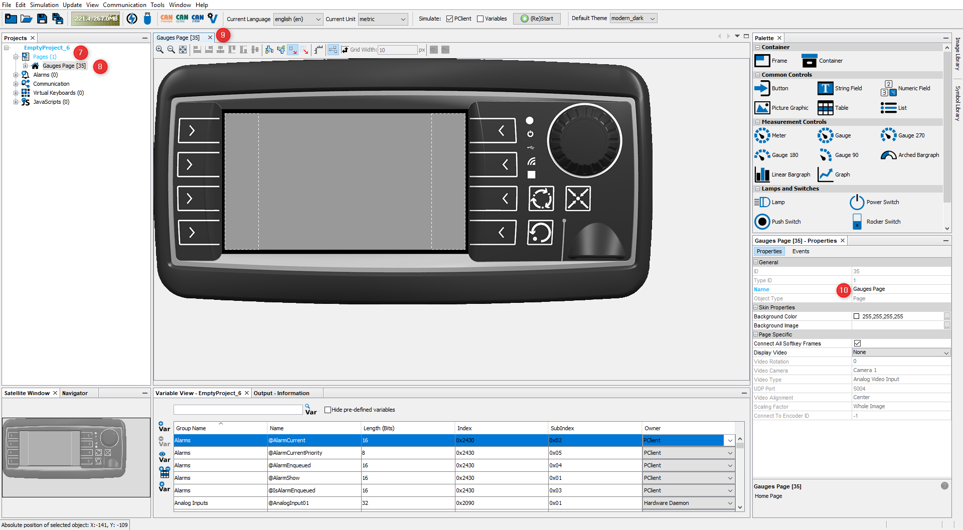
•Double click on project name (7)
•Double click on "Pages" (7)
•Double click the Home Page in the project tree. (8)
•The Home Page Editor opens. (9)
•In the Properties window change the page name into Gauges Page. (10)
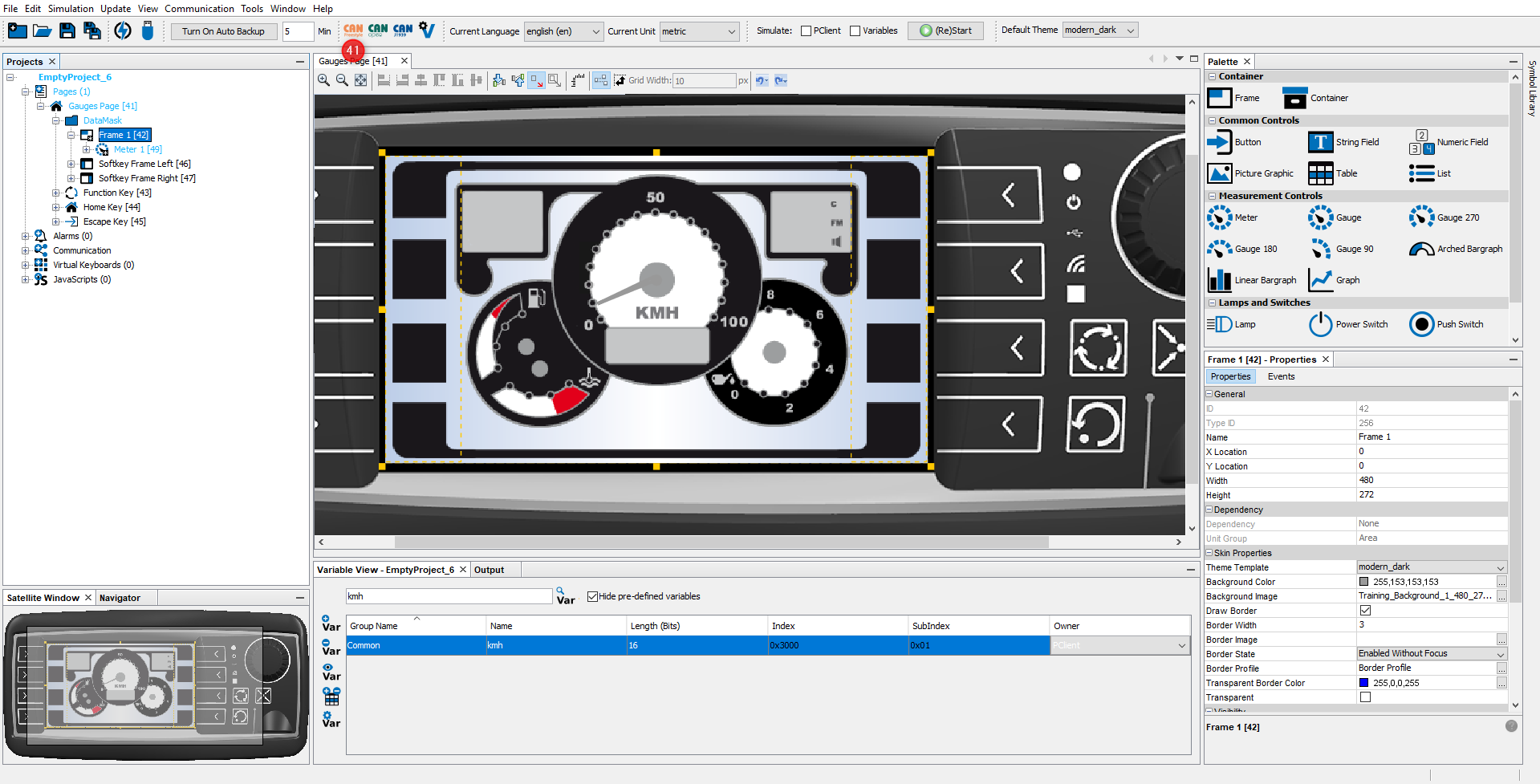
In this tutorial, the basic page layout is given by a background image. To add a background image, open the Image Library tab (11), and use the Browse button (12) to add the folder where the tutorial images were saved. Then select the image Training Background1.png (13) and drag & drop it onto the gray frame in the virtual device (14). Select the Frame 1 and then Background Image.
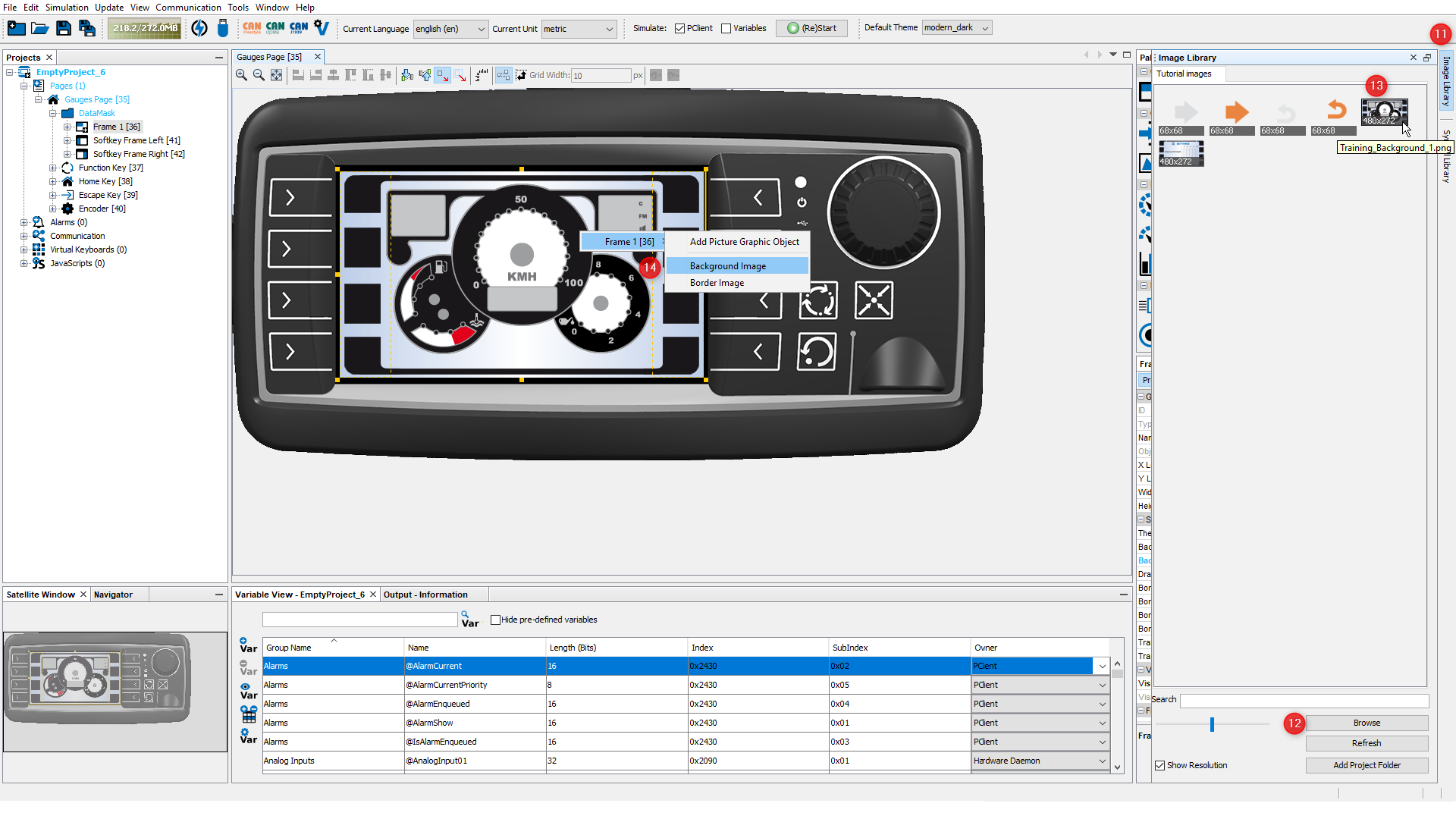
Note that the image now has a suffix _480_272 in the file name . A new instance of the image in this resolution is automatically created.
|
In a next step a new page is added. Further the navigation between the two pages is defined.
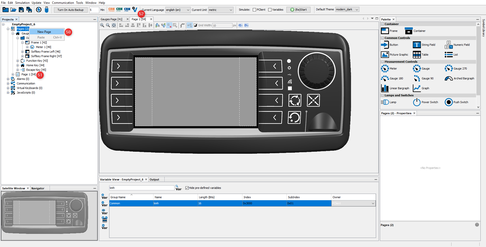
•To create a new page use the right click context menu and choose New Page (50). •A new page with name Page 1 is created (51). •A new editor tab is opened showing the new page Page 1 (52).
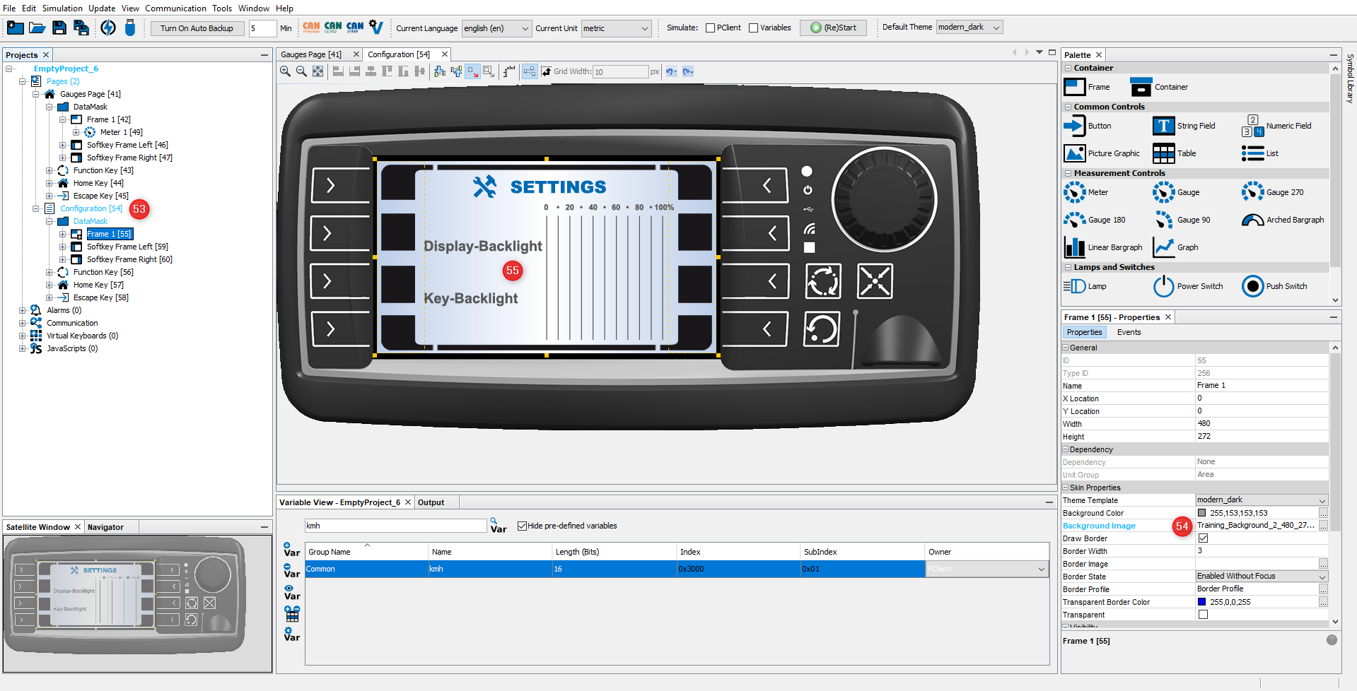
As you did in the first page: •In the Properties window of the page change the name into Configuration (53). •Add the training background 2 image from the Image Library and add it as a background image for the frame (54). •The new page now has the selected background picture (55).
|
The eight keys at the left and right screen border are called softkeys. You can place icons close to the softkeys into the Softkey Frame on the screen to describe the function of each softkey. The function can be triggered by pressing the appropriate key or by pressing the icon on the screen, if a touch screen is available. Softkeys will be used for the navigation between the pages.
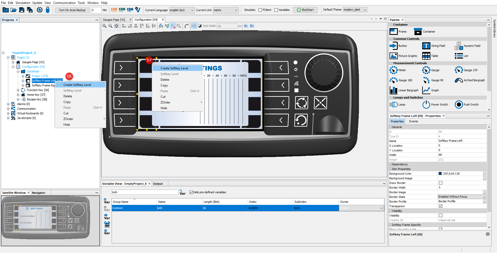
The Softkey Frames for the row of softkeys at the left and right screen border were created automatically. But you still need to create a softkey level to configure the keys. We will start with the Configuration page: •Open the right click context menu of Softkey Frame Left and choose Create Softkey Level (56) •Alternatively you can right-click on the Softkey Frame itself and select Create Softkey Level (57)
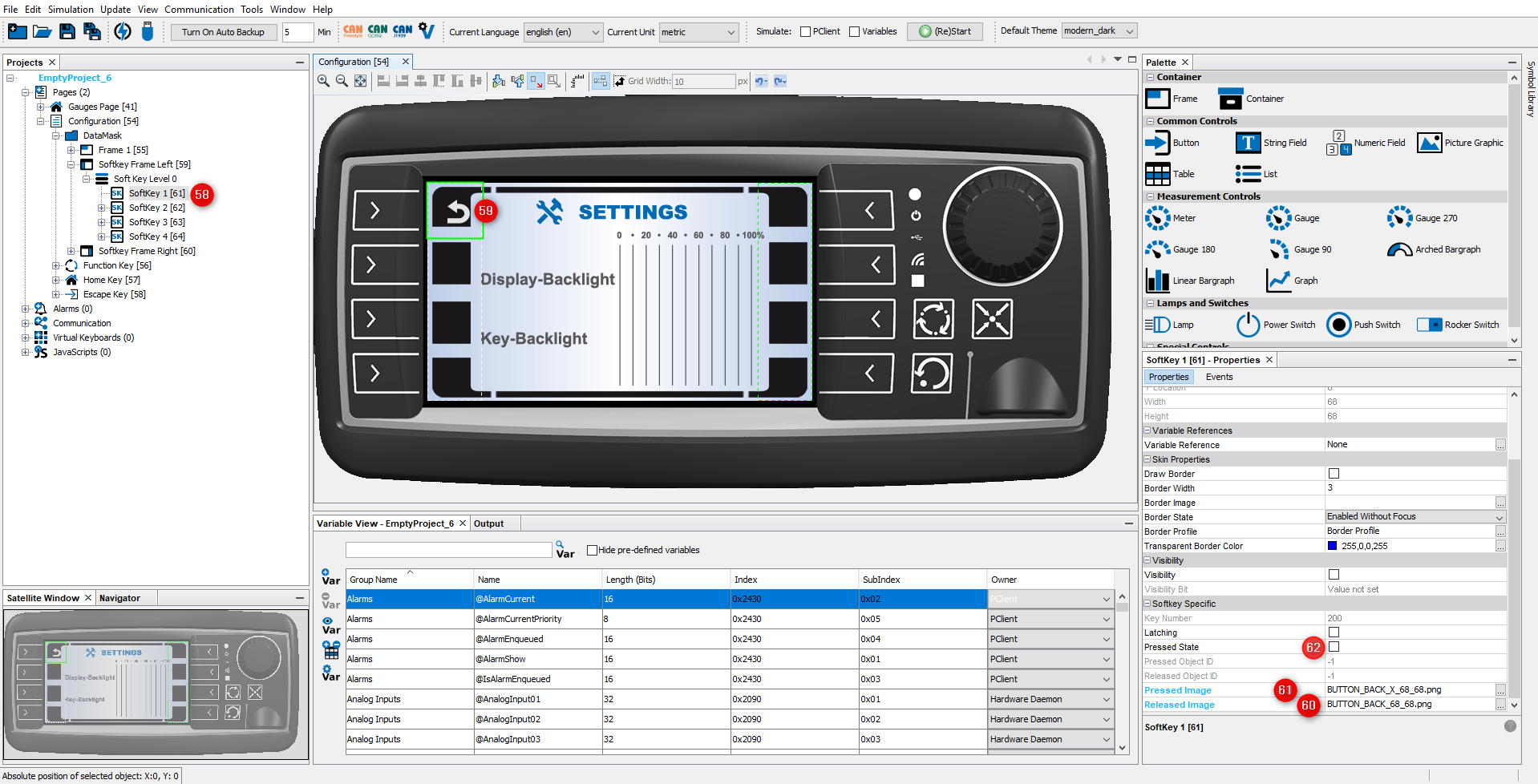
Now we can start configuring the softkeys: •Select the first Softkey in the project tree (58)upper left or in the editor (59) •Drag & drop the file BUTTON_BACK.png from the Image Library on the Softkey, and in the context menu, select the softkey and then Released Image. •Drag & drop the file BUTTON_BACK_pressed.png from the Image Library on the Softkey, and in the context menu, select the softkey and then Pressed Image.
By switching the state of the Pressed State check box (62) you are able to view both softkey states in the editor. Make sure that the property is unchecked at the end.
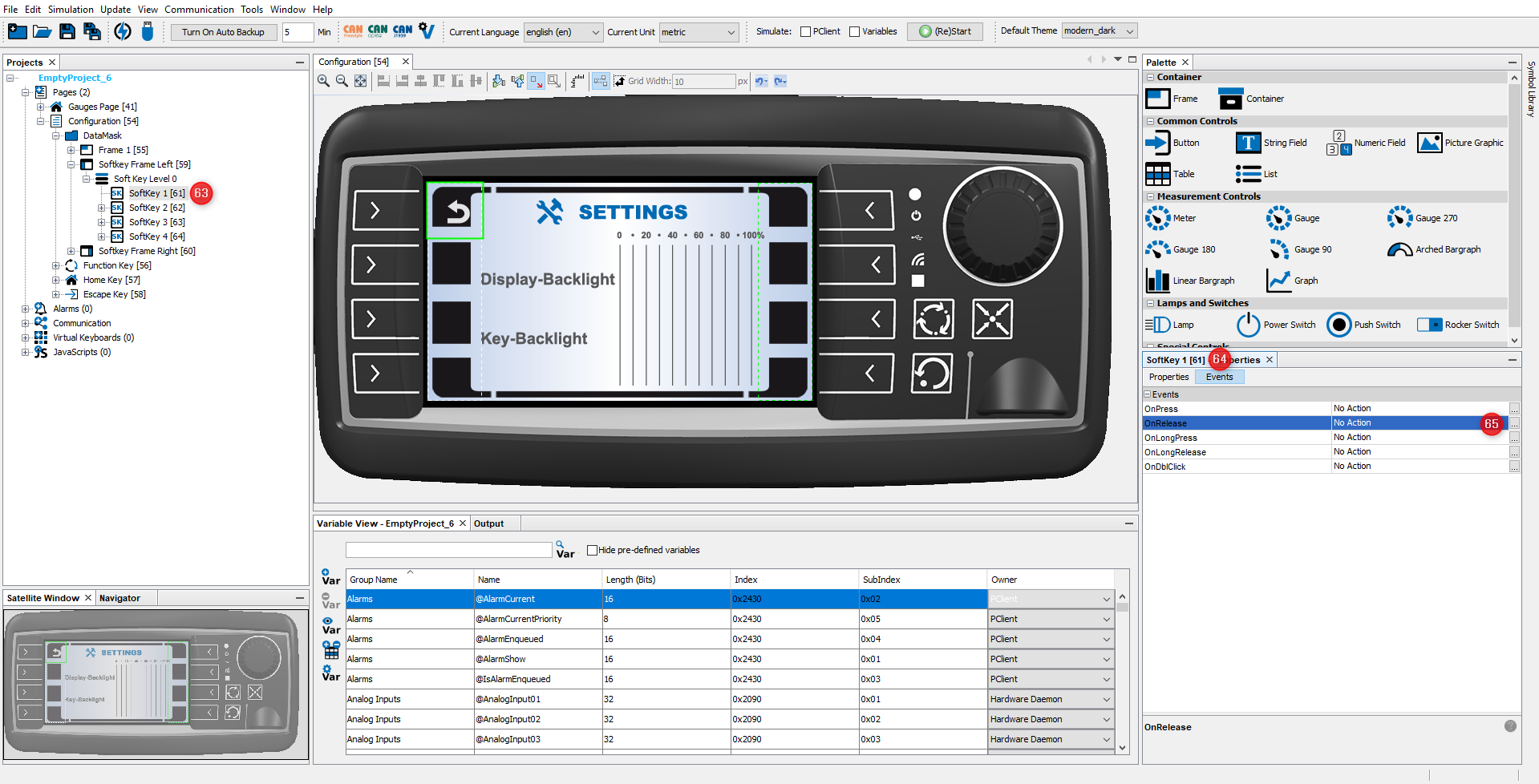
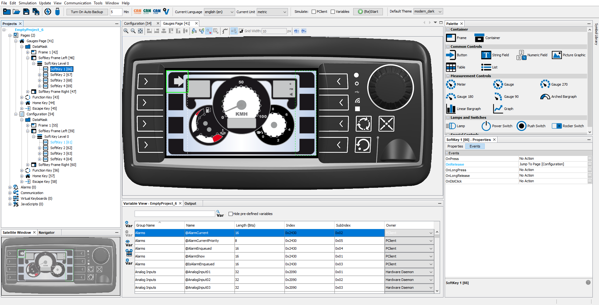
Next step is to define a softkey event. The event should change to the Gauges page when the user presses (or rather, releases) the Softkey you just configured graphically: •Select Softkey 1 in the Projects tree (63). •Open the Events tab by clicking Events in the Properties window (64). •Click the "..." icon of the OnRelease event (65).
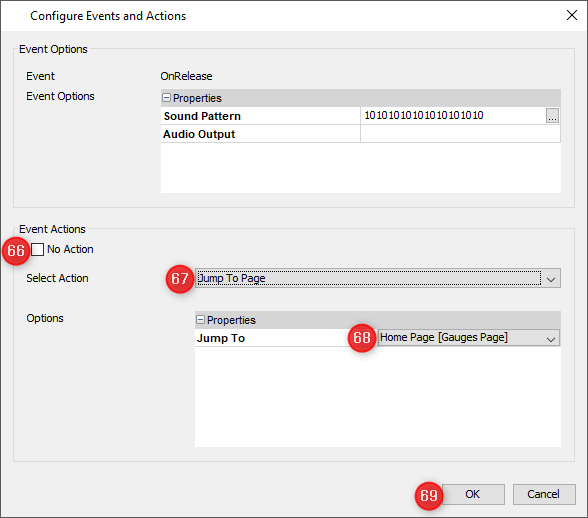
The Configure Events and Actions dialog opens. •Un-check No Action (66). •Select Jump To Page (67). •Choose the Gauges page (67). •Close window by clicking OK button (69).
That's all for the page switch from the Configuration Page to the Gauges page. We added two images, one for press and one for non-pressed state of the softkey. Further we defined the jump to page action for the softkey on the OnRelease event.
For the navigation from the Gauges Page to the Configuration Page please follow the same steps (56 to 69) to configure one of the softkeys of the Configuration page. The result should look like this:
|
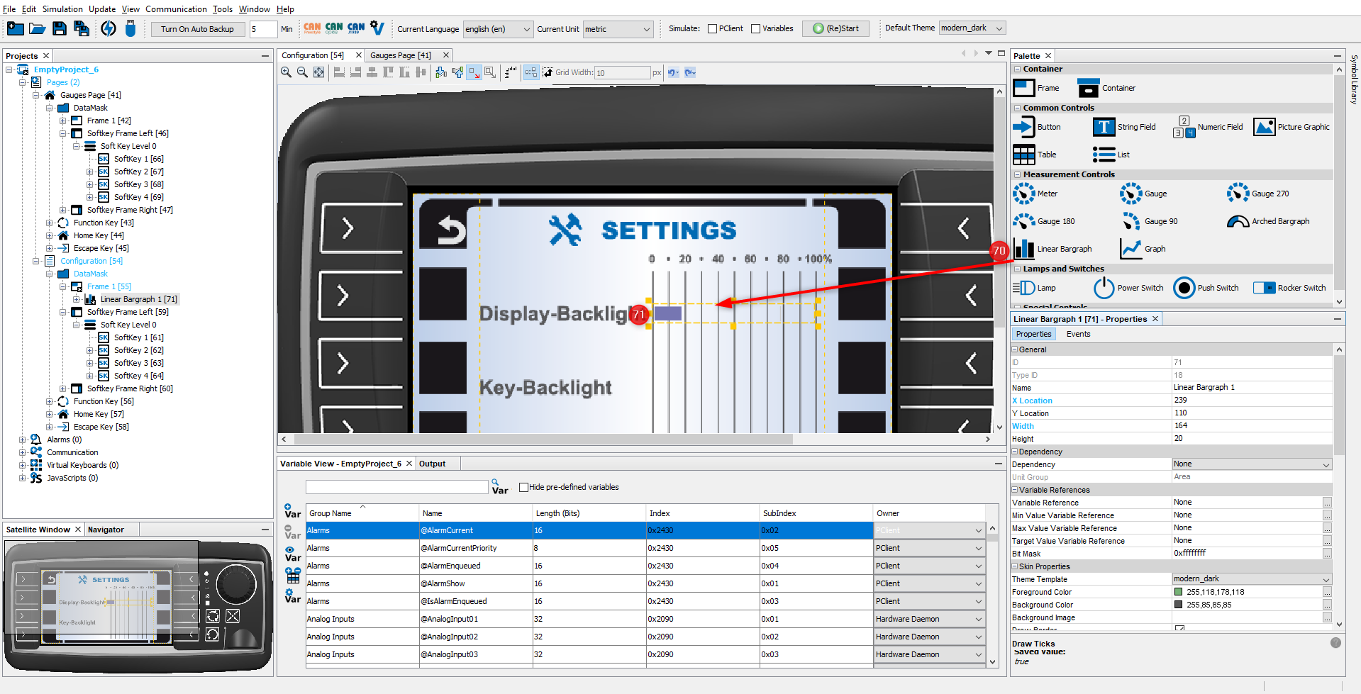
The display user shall be able to change the display backlight intensity. Here is what needs to be done: •Drag the Linear Bargraph from the Palette (70) to the page editor (71).
Change the following Properties of the Linear Bargraph: •X Location: 239 •Y Location: 110 •Width: 164 •Height: 20 •Check Transparent •Check Set As Input •Uncheck Draw Target Line •Uncheck Draw Ticks
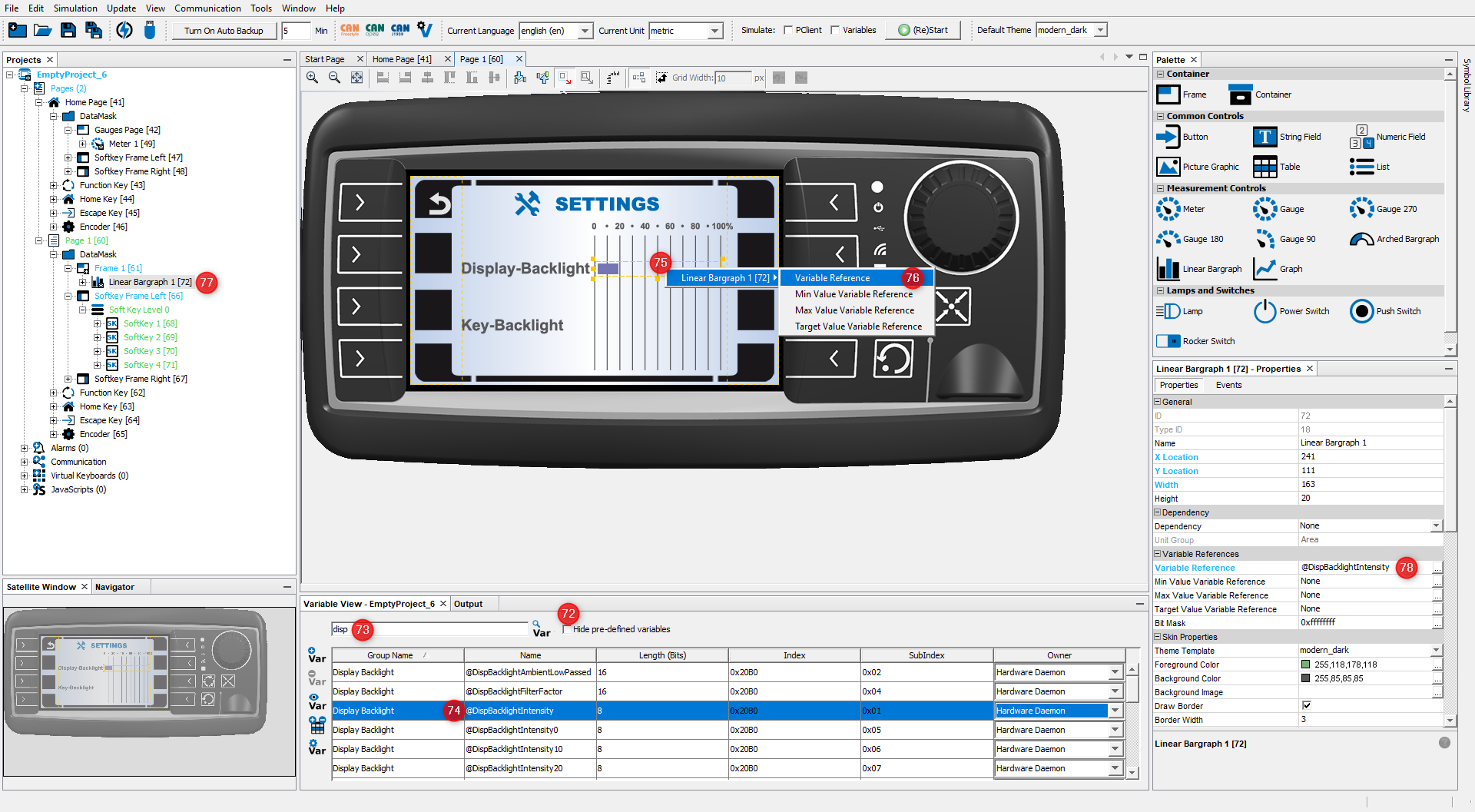
To use the Linear Bargraph to change the display backlight intensity, we need to create a reference from the Linear Bargraph to the pre-defined variable @DispBacklightIntensity: •Uncheck Hide pre-defined variables in the Variable View (72). •In the Variable View search filed enter: disp (73). •Drag the variable @DispBacklightIntensity from Variable View (74) and drop it on the Linear Bargraph (75). Alternatively, you could drop it on the Linear Bargraph entry in the project tree (77) •A context menu appears. In the first level, select the Linear Bargraph 1 object. In the second level, choose Variable Reference (76). •You can now check in the Properties of the object that the variable is set as the Variable Reference (78).
When running the project on a real display device, the user can use the encoder to change the display backlight intensity. The intensity is changed immediately when the user changes the value of the Linear Bargraph. |
