The ISO 17215 standard provides a standardized way to configure ethernet cameras in an automotive environment.
The ISO 17215 ethernet camera configuration tool is a small desktop application that allows configuration of ethernet cameras that support ISO 17215. It is intended for end of line configuration.
To open the tool, select Tools => Camera => ISO 17215 Camera Configuration.
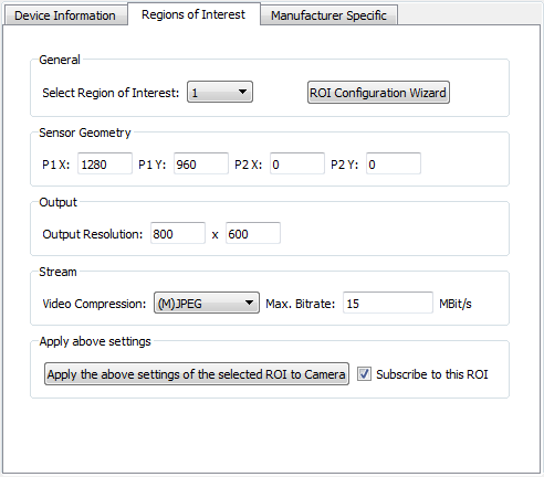
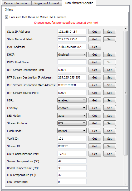
The tool allows retrieving and setting of some of the standardized mandatory settings and also camera manufacturer specific settings if available.
To be able to change camera settings, the tool has to be licensed. See Licensing chapter below for more details.

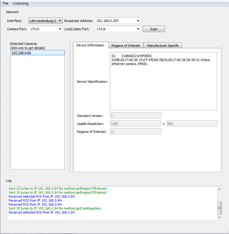
On start up, the tool automatically scans the available ethernet interfaces of the PC and lists them in the Interfaces drop down box. It only lists interfaces that are up and running (e.g. are configured and a cable is connected). Choose the interface to which the camera is connected.
The Broadcast Address field will automatically be filled with the matching IPv4 broadcast address of the chosen interface but can be changed manually if needed. Note that the network address of the interface has to be configured so it matches the network of the camera (e.g. if the camera has the address 192.168.135.16, the interface on the PC should also have an address in the 192.168.135.X network (where X needs to be an unused number, typically 1)).
If the IP address of your network interface can't be changed, consider using a second network card / USB-Ethernet interface.
The Camera Port field needs to contain the UDP communication port number on which the camera listens. This is not the port for the actual video stream but the one for the ISO 17215 communication. Typical values are 17215 (ISO 17215), 30490 (SOME/IP-SD) or 30391 (SOME/IP).
The Local Listen Port field contains the UDP port to which the camera will send its answers (the port on which the PC tool will listen). Typically this is Camera Port + 1.
Refer to the manufacturer documentation of the camera to get the matching addresses and port numbers.
When hitting the Scan button, a service discovery broadcast message is sent on the selected network. If one or more camera answer the request, they will be listed in the Detected Cameras list. |
When a camera is detected, it will be listed in the Detected Cameras list. Select one of the detected IP addresses to select the camera.
The data set of the camera will automatically be requested and the information is presented in the Device Information tab.
|
Check the Log window for message with the tool and the camera. Error messages are shown in red color. Reception messages are shown in blue. Sent messages in green. |
If the OPUS Projektor is not licensed, settings from cameras can be read but no changes can be sent to the camera. Please contact your vendor to obtain a license for the tool. If a license was already obtained and the tool is started from within the program, the existing license file will automatically be provided to the tool. If this tool shall be used as a stand-alone version, existing customers may also send a license request to the vendor. This request needs to contain the key file which can be generated via Licensing => Generate Key File. The vendor will return a license file which can be loaded via Licensing => Load License File. The location of the license file will be remembered and only needs to be done once (or whenever the license file is moved on the file system). |


